5 vdc output wiring (24 vac power), Humidity sensor rh/voltage chart – Orion System OE217-00 User Manual
Page 23
JOB NAME
FILE NAME
G-OE265-11-SPHUMID1D.PDF
DATE: 08/02/07
PAGE
DESCRIPTION
OE265-11
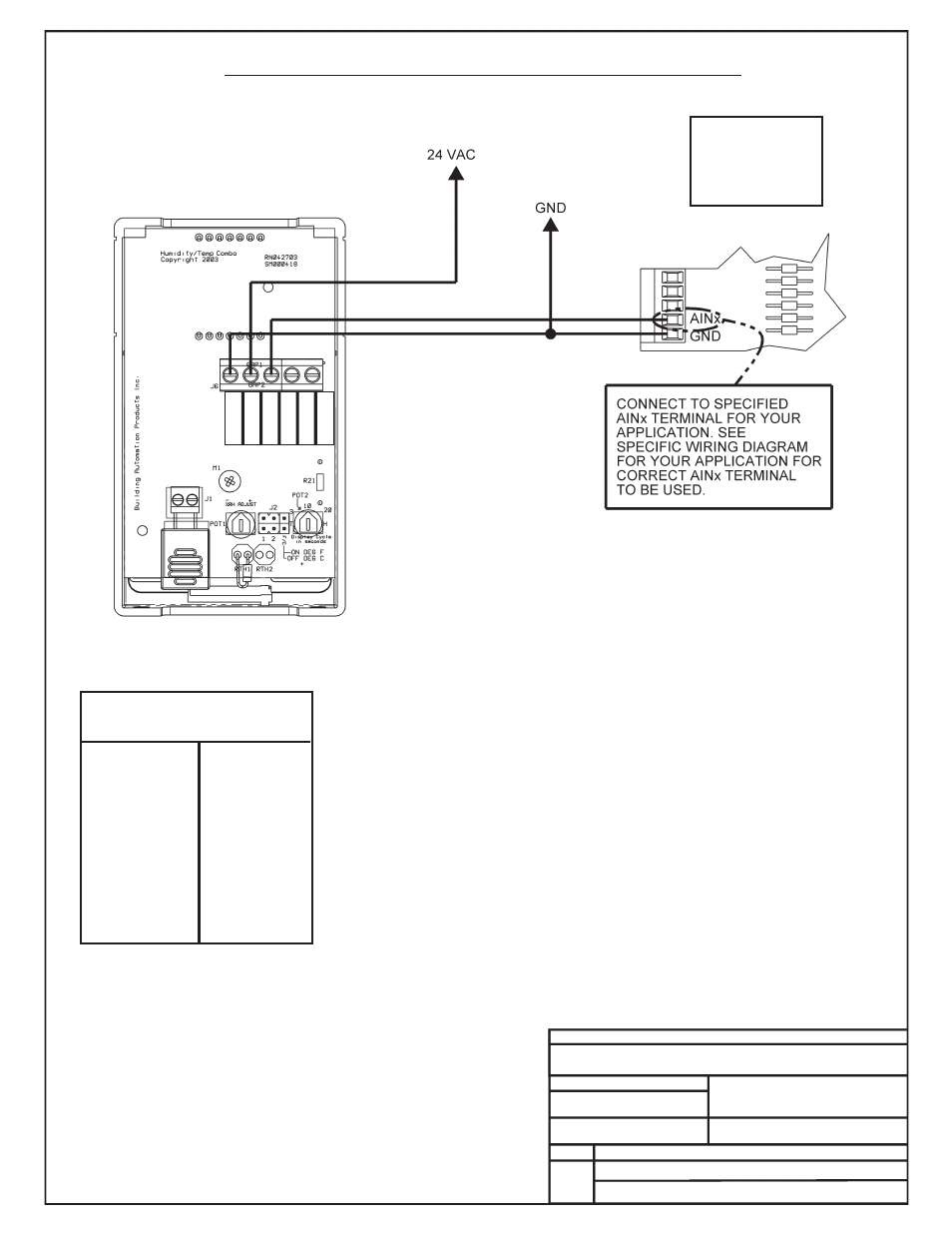
Space Humidity Sensor – 0-5 VDC
DRAWN BY: B. CREWS
*Chart Notes:
1. First, be sure that +24VAC power is being supplied to the sensor. Second, set the
meter to DC volts and connect the meter between ground and the 0-5 VDC input
terminal on the controller board or between the 0-5 VDC output terminal on the
sensor and its ground terminal. Use an accurate humidity measurement device to
determine RH (relative humidity) such as an aspirating psychrometer. Use the
Output VDC column to read the Output Voltage corresponding with the RH
percentage measured with the psychrometer. If the measured voltage is within 3%
of what is listed for the corresponding RH, then the sensor is functioning properly.
2 of 2
Notes:
1.) All Wiring To Be In Accordance With Local And
National Electrical Codes And Specifications.
RH
Output
%
VDC
55 ........ 2.75
60 ........ 3.00
65 ........ 3.25
70 ........ 3.50
75 ........ 3.75
80 ........ 4.00
85 ........ 4.25
90 ........ 4.50
95 ........ 4.75
100 ........ 5.00
RH
Output
%
VDC
5 .......... 0.25
10 .......... 0.50
15 .......... 0.75
20 .......... 1.00
25 .......... 1.25
30 .......... 1.50
35 .......... 1.75
40 .......... 2.00
45 .......... 2.25
50 .......... 2.50
Humidity Sensor
RH/Voltage Chart
Warning
Be Sure To Observe
Polarity Or Serious
Damage To The
Board Could Result
0-5 VDC Output Wiring (24 VAC Power)
0-5VD
CT
erminal
Label:
LB101969
Gnd
Vin Vo
Not
Used
Not
Used