5 vdc output wiring (24 vac power), Humidity sensor rh/voltage chart – Orion System OE217-00 User Manual
Page 21
JOB NAME
FILE NAME
PAGE
DESCRIPTION
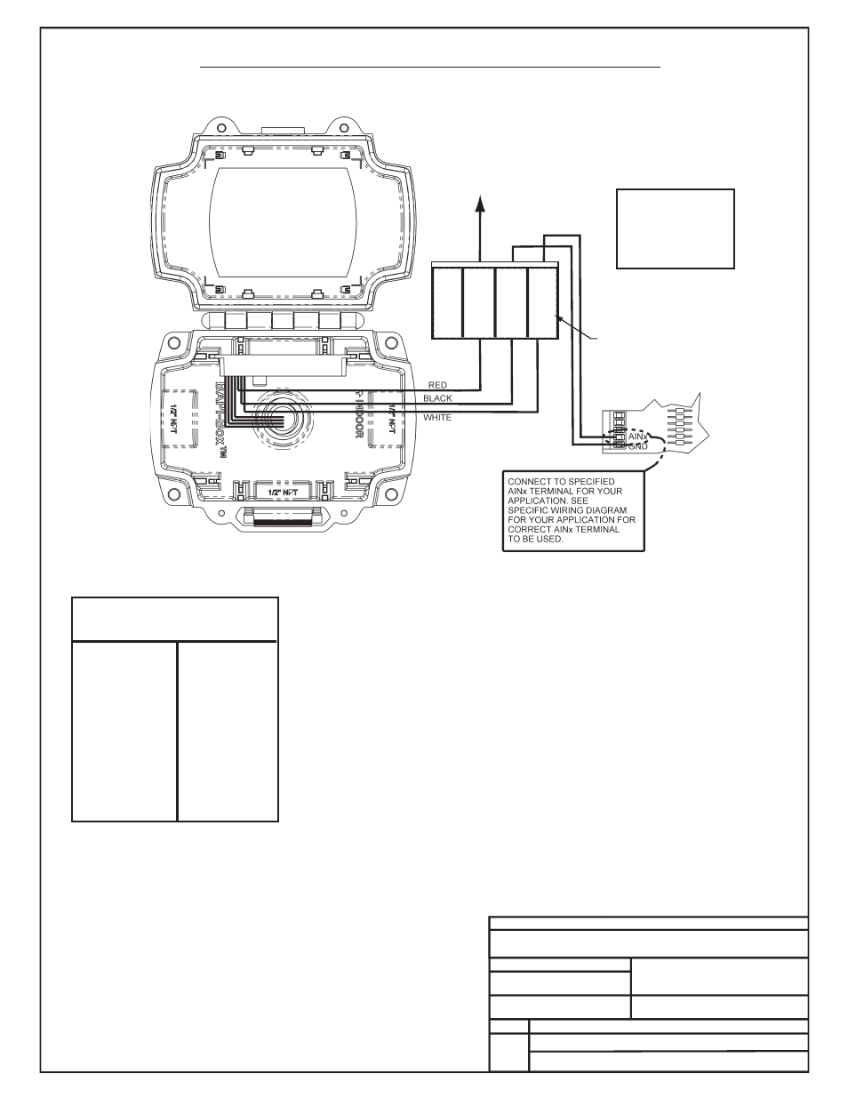
Return Air Humidity Sensor – 0-5 VDC
DRAWN BY: B. CREWS
2 of 2
RH
Output
%
VDC
55 ........ 2.75
60 ........ 3.00
65 ........ 3.25
70 ........ 3.50
75 ........ 3.75
80 ........ 4.00
85 ........ 4.25
90 ........ 4.50
95 ........ 4.75
100 ........ 5.00
RH
Output
%
VDC
5 .......... 0.25
10 .......... 0.50
15 .......... 0.75
20 .......... 1.00
25 .......... 1.25
30 .......... 1.50
35 .......... 1.75
40 .......... 2.00
45 .......... 2.25
50 .......... 2.50
Humidity Sensor
RH/Voltage Chart
Warning
Be Sure To Observe
Polarity Or Serious
Damage To The
Unit Could Result
0-5 VDC Output Wiring (24 VAC Power)
G-OE265-14B-RAHUMID-1D.PDF
DATE: 08/28/07
OE265-14 BAPI
Notes:
1.) All Wiring To Be In Accordance With Local And
National Electrical Codes And Specifications.
*Chart Notes:
1. First, be sure that +24VAC power is being supplied to the sensor. Second check the
sensor output. Set the meter to DC volts and connect the meter between ground
and the 0-5 VDC input terminal on the controller board or between the 0-5 VDC
output on the sensor and its ground wire or you can measure voltage at the 0-5 VDC
and GND terminals on the sensor located at the sensor installtion location.
After measuring the voltage use an accurate humidity measurement device to
determine RH (relative humidity) such as an aspirating psychrometer. Use the
Output VDC column to read the Output Voltage corresponding with the RH
percentage measured with the psychrometer. If the measured voltage is within 3%
of what is listed for the corresponding RH, then the sensor is functioning properly.
CONNECT TO
24 VAC POWER
0-5VDC
Terminal
Label:
LB101966
RED
BLK
WHT
Not
Used
VA
Co
rD
C
GND
0-5V
SENSOR TERMINAL
BLOCK