Skutch Electronics AS-6 User Manual
Introduction, Installation, Tele-line/simulator modes
•
Introduction
The AS-6 is the perfect solution for applications that require frequent
prompt recording. The AS-6 allows the user to access their voice system
without tying up valuable phone lines. The unit has both mic and line level
inputs so that a wide variety of audio sources can be used to down load audio
prompts on to your voice system. The AS-6 has an 8 LED audio level meter
and an adjustable INPUT LEVEL control that helps the user make consistent
high quality recordings. The AS-6 does not provide any EQ or tone
adjustments, so all EQ must implemented before the signal is applied to the
AS-6.
A standard single line telephone can be used to monitor the audio
recordings. The MUTE button on the AS-6 allows you to monitor with the
phone without inserting any ambient noises. If you need to have a speaker
type monitor, you can use a phone that has a speakerphone function.
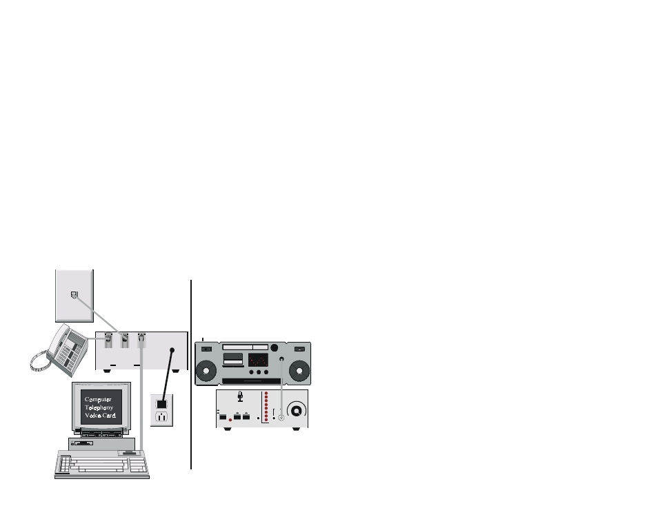
The AS-6 is installed between the telephone line and your voice card.
When local access is required, the TELE-LINE/SIMULATOR switch is
depressed, and the RING UP button can be used to supply a ring signal to the
voice channel. The AS-6 places a BUSY condition on the telephone line
during local access, so that no calls will go unanswered.
•
Installation
1) Connect a modular telephone cord from your voice card to the jack on
the back of the AS-6 labeled VOICE CARD. The jacks on the AS-6 are
wired for RJ-14, which is a 2 line jack. The AS-6 uses the 1st line
position and passes the second through.
2) Connect another modular cord to the jack on the back of the AS-6
labeled TELEPHONE LINE, and connect the other end to your
telephone line jack.
3) Connect the modular cord from a single line telephone to the jack on the
back of the AS-6 labeled PHONE.
4) Connect the power cord from the AS-6 to any standard 110VAC power
outlet.
•
Tele-Line/Simulator Modes
The TELE-LINE/SIMULATOR switch determines whether the voice
channel is connected to the AS-6 SIMULATOR or the telephone line. When
the switch is OUT, the voice channel is connected to the telephone line.
When the switch is in, the voice channel is connected to the AS-6
SIMULATOR. The VC IN-USE led indicates if the voice channel is
currently "OFF HOOK" or IN-USE. If the IN-USE light is on, this indicates
that a call is in progress and you should wait until it goes out before
switching the voice channel to the AS-6 SIMULATOR; otherwise you will
interrupt the call.
When you switch to the AS-6 SIMULATOR mode, the AS-6
automatically places a BUSY condition on the telephone line. This insures
that no caller will get a ring-no-answer condition; thus no call will go
unanswered. The BUSY condition is maintained until the AS-6 is switched
back to the TELE-LINE position. The BUSY condition can be disable with a
jumper that is located on the printed circuit board.
•
Ring Up
Either the local phone must be "OFF HOOK", or the MUTE switch
must be engaged in order to establish a simulated call. This switch is used to
supply a simulated ring condition to the voice channel. To simulate a ring,
simply depress the switch for approximately 2 seconds then release. If your
voice channel is programmed to answer on 3 rings, you would have to press
the switch three times before the channel would respond.
M ad e in th e U S A
V o ic e C a rd
P h o n e
Te le p h o n e
L in e
Wall
Phone
Jack
Lines 1 & 2
Message Source
Head
Phones
A S -6 B ac k
A S -6 Fro n t
A S -6
Telep h o n e L in e S im u lato r
S im u la to r
Tele-Lin e
V C In -U se
R in g U p M u te
A u d io
O u tp u t
In p u t
In p u t Lev el
Lin e
M ic
Le vel
+ 3
+ 2
+ 1
0
-1
-3
-5
-7
m in
m a x