Super Systems 7EK 31082 User Manual
Page 10
5
GB
SERIAL INTERFACE
RS-485 interface allows to connect up to 30 devices with
one remote master unit.
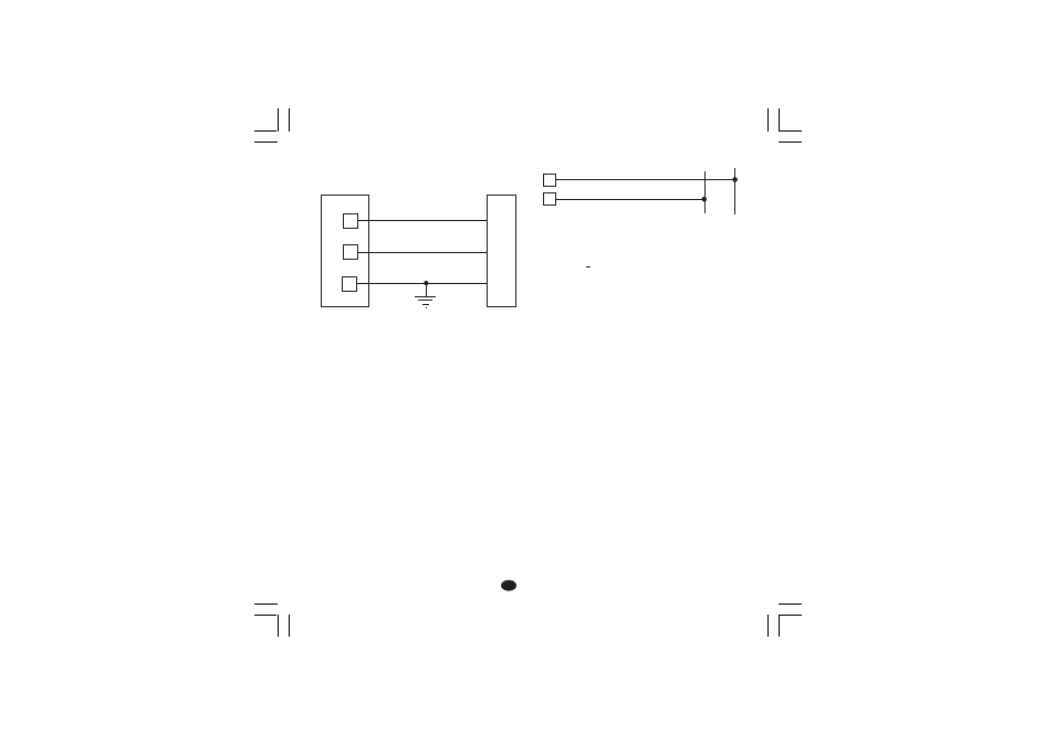
Fig. 9 - RS-485 WIRING
The cable length must not exceed 1.5 km at 9600 BAUD.
It is an isolated RS-485 interface.
Interface type: isolated RS-485
Protocol types: MODBUS, JBUS, ERO polling/selecting.
Baud rate: programmable from 600 to 19200 BAUD.
Byte format: 7 or 8 bit programmable.
Parity: even, odd or none programmable.
Stop bit: one.
Address:
-
from 1 to 95 for ERO protocol
-
from 1 to 255 for all the other protocols
Output voltage levels: according to EIA standard.
NOTE: The following report describes the signal sense of
the voltage appearing across the interconnection
cable as defined by EIA for RS-485.
a) The ” A ” terminal of the generator shall be
negative with respect to the ” B ” terminal for a
binary 1 (MARK or OFF) state.
b) The ” A ” terminal of the generator shall be
positive with respect to the ” B ” terminal for
a binary 0 (SPACE or ON).
E) POWER LINE WIRING
Fig. 10 POWER LINE WIRING
100V to 240V AC 50/60Hz (-15% to + 10% of the nominal
value).
24 V AC/DC (+ 10 % of the nominal value).
NOTE:
1) Before connecting the instrument to the power line, make
sure that line voltage corresponds to the descrtiption on
the identification label.
2) To avoid electric shock, connect power line at the end of
the wiring procedure.
3) For supply connections use No 16 AWG or larger wires
rated for at last 75 °C.
4) Use copper conductors only.
5) Don't run input wires together with power cables.
6) For 24 V DC the polarity is a do not care condition.
7) The power supply input is fuse protected by a sub
miniature fuse rated T, 1A, 250 V.
When fuse is damaged, it is advisable to verify the
power supply circuit, so that it is necessary to send
back the instrument to your supplier.
8) The safety requirements for Permanently Connected
Equipment say:
- a switch or circuit-breaker shall be included in the
building installation;
- It shall be in close proximity to the equipment and within
easy reach of the operator;
- it shall be marked as the disconnecting device for the
equipment.
NOTE: a single switch or circuit-breaker can drive more
than one instrument.
9) When a neutral line is present, connect it to terminal
13.
10
9
COMMON
11
B'/B
B/B'
A/A'
A'/A
M
A
S
T
E
R
I
N
S
T
R
U
M
E
N
T
12
13
N (L2)
L (L1)
N (L2)
L (L1)
XKSser1-A0.p65
10/19/01, 1:37 PM
5