Super Systems 7EK 31082 User Manual
Page 8
3
GB
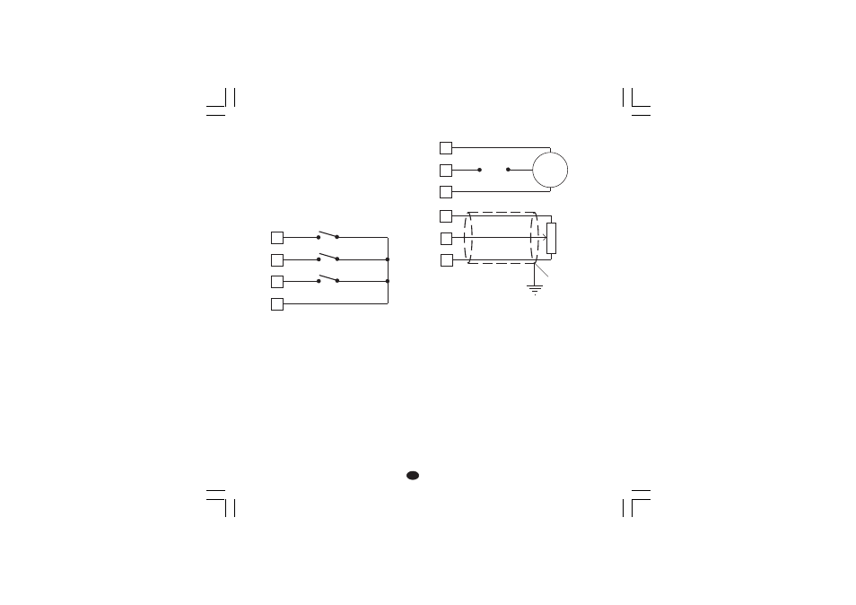
B) LOGIC INPUT
Safety note:
1) Do not run logic input wiring together with power
cables.
2) Use an external dry contact capable of switching 0.5
mA, 5 V DC.
3) The instrument needs 100 ms to recognize a contact
status variation.
4) The logic inputs are NOT isolated by the measuring
input. A duble or reinforced isolation between logic
inputs and power supply must be assured by the
external elements.
Fig. 5 - LOGIC INPUT WIRING
This instrument is provided with 3 logic inputs.
The binary combination of the logic input 1 and 3 allows to
select the operative set point according with the following
table:
logic input 3
logic input 1
op. set point
open
open
SP
open
close
SP2
close
open
SP3
close
close
SP4
The logic input 2 function is programmed by P 24
parameter.
C) VALVE MOTOR DRIVE OUTPUT.
Fig. 6 - SERVOMOTOR WIRING
The two relay outputs are interlocked.
Potentiometer type: from 100
W to 10 kW.
Minimum working stroke: 50 % of the potentiometer
rang in order tu assure the 1% display resolution.
NOTES:
1) Before connecting the instrument to the power line, make
sure that line voltage and the load current are in accord-
ance with the contact rating (3A/250V AC on resistive
load).
2) To avoid electric shock, connect power line at the end of
the wiring procedure.
3) For servomotor connections use No 16 AWG or larger
wires rated for at last 75 °C.
4) Use copper conductors only.
5) Don’t run input wires together with power cables.
6) For feedback potentiometer, use shielded cable with the
shield connected to the earth at one point only.
7) The relay outputs are protected by varistor against
inductive load with inductive component up to 0.5 A.
8
Log. input 3
7
Log. input 2
6
5
Log. input 1
17
18
19
Servo-
motor
Power
line
20
21
22
s (Open the valve)
t (Close the valve)
Feedback
potentiometer
Shield
XKSser1-A0.p65
10/19/01, 1:37 PM
3