Super Systems 7EK 31082 User Manual
Page 9
4
GB
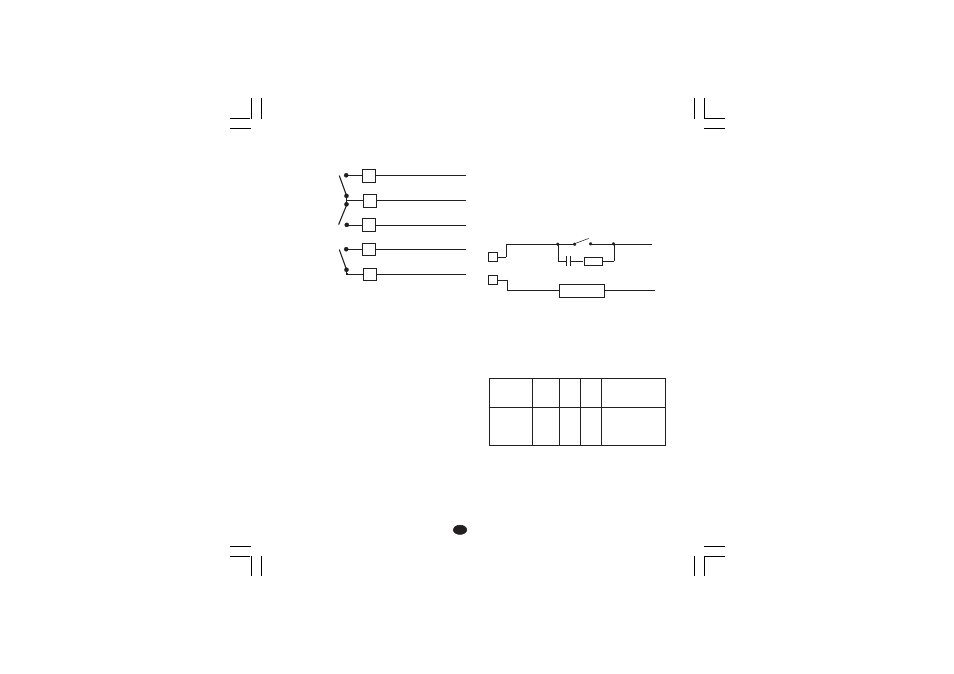
INDUCTIVE LOADS
High voltage transients may occur when switching
inductive loads.
Through the internal contacts these transients may
introduce disturbances which can affect the performance
of the instrument.
The internal protection (varistor) assures a correct protection
up to 0.5 A of inductive component.
The same problem may occur when a switch is used in
series with the internal contacts as shown in Fig. 8.
Fig. 8 EXTERNAL SWITCH IN SERIES WITH THE
INTERNAL CONTACT
In this case it is recommended to install an additional RC
network across the external contact as shown in Fig. 10
The value of capacitor (C) and resistor (R) are shown in
the following table.
Anyway the cable involved in relay output wiring must be
as far away as possible from input or communication
cables.
16
14
15
C - OUT 3/4
NO - OUT 3
NO - OUT 4
OUT 3
OUT 4
LOAD
(mA)
<40 mA
<150 mA
<0.5
A
C
(
mF)
0.047
0.1
0.33
R
(
W)
100
22
47
P.
(W)
1/2
2
2
OPERATING
VOLTAGE
260 V AC
260 V AC
260 V AC
17
18
C
NO
OUT 1
D) RELAY OUTPUTS
Fig. 7 RELAY OUTPUTS WIRING
NOTE: OUT 1 can be used either as servomotor output or
as time proportional relay output; by the P5
parameter (see pag.11) it is possible to set the
desired output.
All relay outputs are protected by varistor against inductive
load with inductive component up to 0.5 A.
The contact rating of OUT 1 is 3A/250V AC on resistive
load, the contact rating of OUT 3 and 4 is 2A/250V AC on
resistive load.
The contact rating of the OUT 3 and 4 is 2A/250V AC resistive
load.
The number of operations is 1 x 10
5
at specified rating.
Alarm 2 and alarm 3 are in OR condition on the out 4.
The following recommendations avoid serious problems
which may occur, when using relay output for driving
inductive loads.
R
C
LOAD
POWER
LINE
XKSser1-A0.p65
10/19/01, 1:37 PM
4