Super Systems 7EK 31082 User Manual
Page 6
1
GB
MOUNTING REQUIREMENTS
This instrument is intended for permanent installation, for
indoor use only, in an electrical panel which encloses the
rear housing, exposed terminals and wiring on the back.
Select a mounting location where there is minimum
vibration and the ambient temperature range between 0
and 50 °C.
The instrument can be mounted on a panel up to 15 mm
thick.
For outline and cutout dimensions refer to page IV.
The surface texture of the panel must be better than
6,3
mm.
The instrument is shipped with rubber panel gasket.
To assure the IP65 and NEMA 4 protection, insert the
panel gasket between the instrument and the panel as
shown in fig. 1.
While holding the instrument against the panel proceed as
follows:
1) insert the gasket in the instrument case;
2) insert the instrument in the panel cutout;
3) pushing the instrument against the panel, insert the
mounting bracket;
4) with a screwdriver, turn the screws with a torque
between 0.3 and 0.4 Nm.
panel
bracket
screw
Fig. 1
gasket
screw
bracket
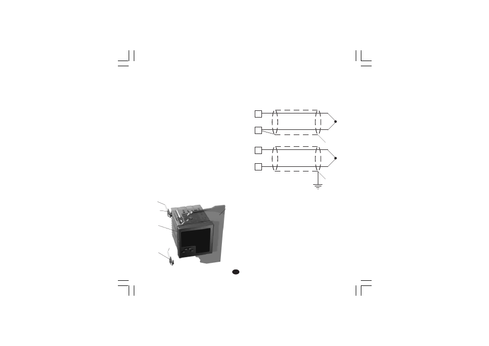
CONNECTIONS
A) MEASURING INPUT
NOTE: Any external components (like zener barriers etc.)
connected between sensor and input terminals may cause
errors in measurement due to excessive and/or not
balanced line resistance or possible leakage currents.
TC INPUT
Fig. 2 THERMOCOUPLE INPUT WIRING
External resistance: 100
W max, maximum error 0,1% of
span.
Cold junction: automatic compensation from 0 to 50 °C.
Cold junction accuracy : 0.1 °C/°C
Input impedance: > 1 M
W
Calibration : according to IEC 584-1 and DIN 43710 -
1977.
NOTE:
1)
Don’t run input wires together with power cables.
2)
For TC wiring use proper compensating cable
preferable shielded.
3)
when a shielded cable is used, it should be connected
at one point only.
Shield
Shield
1
3
+
_
1
3
+
_
XKSser1-A0.p65
10/19/01, 1:37 PM
1