Appendix #2 – ARM Electronics RT4CD User Manual
Page 54
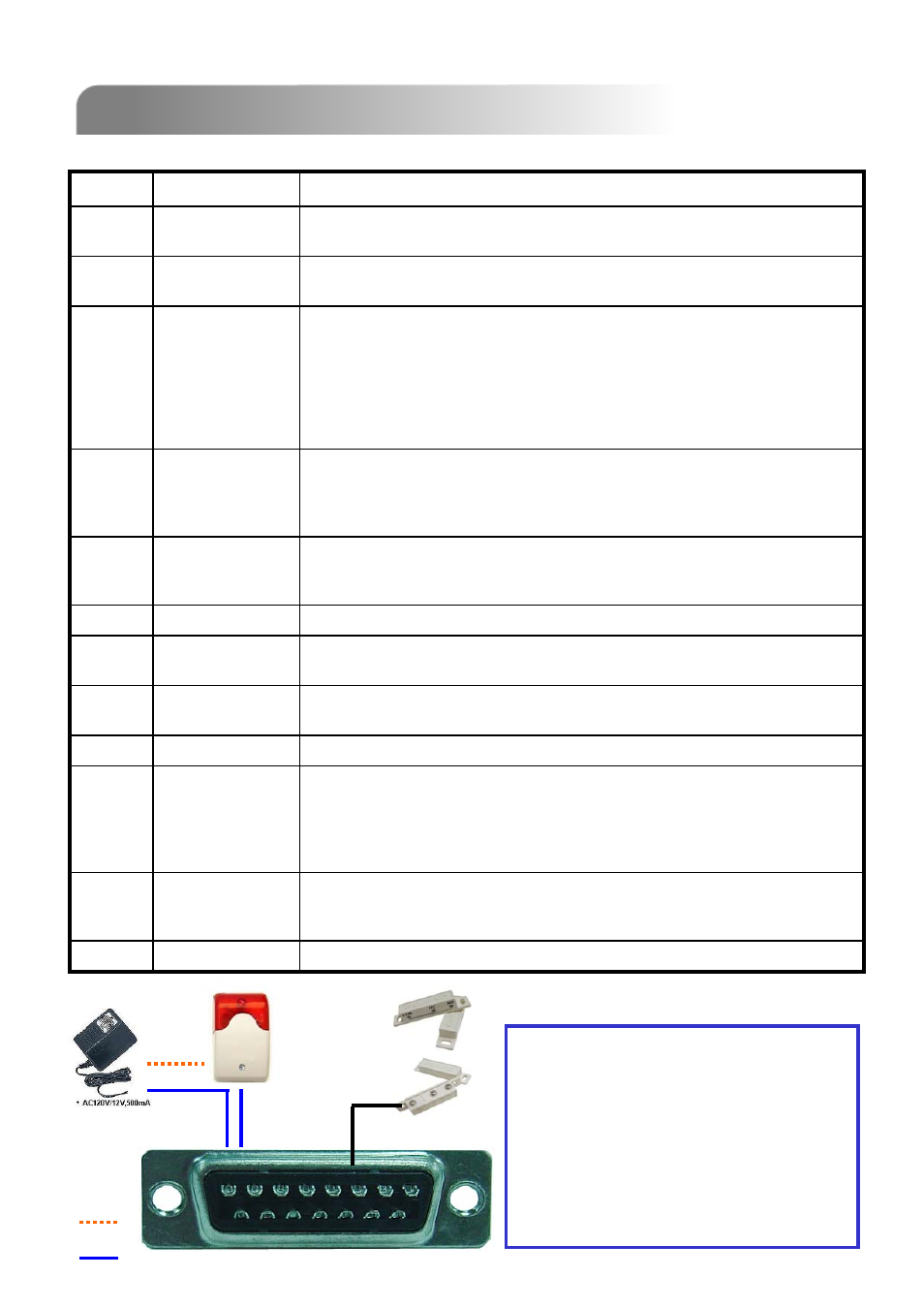
DC12V +
GND
8 7 6 5 4 3 2 1
15 14 13 12 11 10 9
16 17
PIN Connection Application
Solder Side
of DSUB
15PIN
APPENDIX #2
APPENDIX #2
APPENDIX #2
APPENDIX #2
–
–
PIN CONFIGURATION
PIN CONFIGURATION
51
Under the normal operation, COM disconnects with NO. But when any alarm is
triggered, COM connects with NO.
Attention: The voltage restriction is under AV/DC 30V.
EXTERNAL
ALARM COM
15
Earth GND
GND
16~17
Connecting the wire from ALARM RESET (PIN 14) to GND (PIN 9) connector
will disable alarms. An external signal to ALARM RESET (PIN 14) can be used
to reset both ALARM OUTPUT signal and DVR’s internal buzzer. When any
alarm has been triggered, the signal becomes “Low”, and all alarm activities will
be stopped. Under the normal operation, the signal remains “High”.
ALARM RESET
14
PIN OFF
12~13
DVR can be controlled remotely by the keyboard of PC by using RS-485 serial
communication signals.
RS485-A
11
DVR can be controlled remotely by the keyboard of PC by using RS-485 serial
communication signals.
RS485-B
10
Signal GND.
GND
9
Under the normal operation, COM disconnects with NO. But when any alarm is
triggered, COM connects with NO.
Attention: The voltage restriction is under AV/DC 30V.
EXTERNAL
ALARM NO.
8
Under the normal operation, COM connects with NC and disconnects from NO.
But when any alarm is triggered, COM disconnects with NC and connects with
NO.
Attention: The voltage restriction is under AV/DC 30V.
EXTERNAL
ALARM NC
7
To connect the wire from ALARM INPUT ( PIN 3 -- 6 ) to GND ( PIN 9 )
connector, DVR will start recording and the buzzer will be on.
When “MENU -> CAMERA -> ALARM” is set to “Low” : When the alarm input
signal is “ Low ”, the unit starts to record and buzzer.
When “MENU -> CAMERA -> ALARM” is set to “High” : When the alarm input
signal is “ High ”, the unit starts to record and buzzer.
ALARM INPUT
3~6
DVR can be controlled remotely by the keyboard of PC by using RS-232 serial
communication signals.
RS232-RX
2
DVR can be controlled remotely by the keyboard of PC by using RS-232 serial
communication signals.
RS232-TX
1
DESCRIPTION
FUNCTION
PIN
When the magnetic contact is opened, the
alarm will be triggered and the recording is
on. At the same time, COM connects with
NO and the siren with strobe starts wailing
and flashing.
NOTE: Please go to MENU -> ADVANCE ->
DETECTION -> DETECTION SETUP, and
set ALARM to LOW on the local machine.
DC12V +
GND