Configuration procedure, Configuring the tcp buffer size, Configuring tcp timers – H3C Technologies H3C S12500-X Series Switches User Manual
Page 163
152
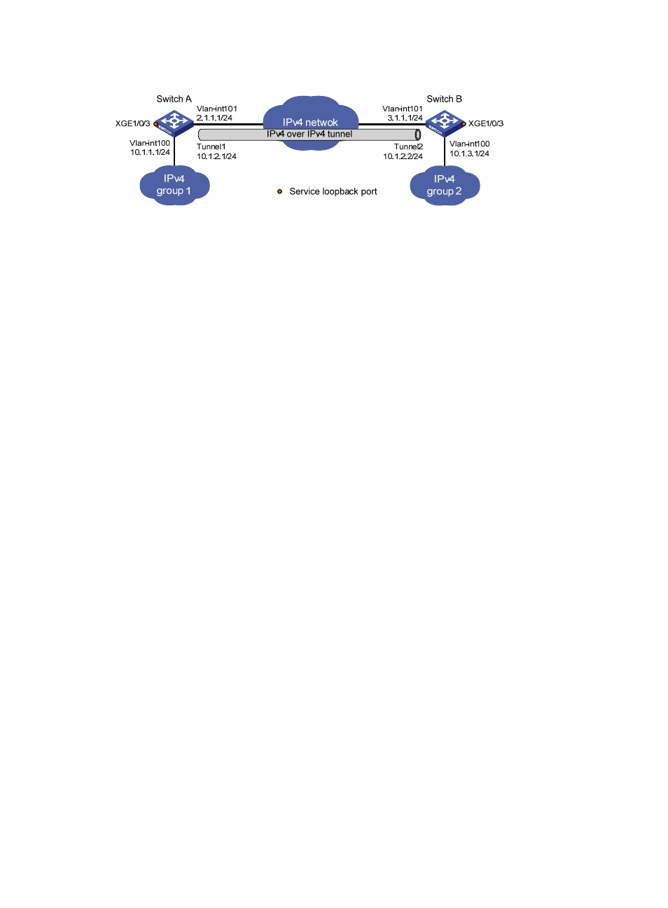
Figure 58 Network diagram
Configuration procedure
Make sure Switch A and Switch B have the corresponding VLAN interfaces created and can reach each
other through IPv4.
•
Configure Switch A:
# Specify an IPv4 address for VLAN-interface 100.
<SwitchA> system-view
[SwitchA] interface vlan-interface 100
[SwitchA-Vlan-interface100] ip address 10.1.1.1 255.255.255.0
[SwitchA-Vlan-interface100] quit
# Specify an IPv4 address for VLAN-interface 101, which is the physical interface of the tunnel.
[SwitchA] interface vlan-interface 101
[SwitchA-Vlan-interface101] ip address 2.1.1.1 255.255.255.0
[SwitchA-Vlan-interface101] quit
# Create service loopback group 1 and specify its service type as tunnel.
[SwitchA] service-loopback group 1 type tunnel
# Assign Ten-GigabitEthernet 1/0/3 to service loopback group 1.
[SwitchA] interface Ten-GigabitEthernet 1/0/3
[SwitchA-Ten-GigabitEthernet1/0/3] port service-loopback group 1
[SwitchA-Ten-GigabitEthernet1/0/3] quit
# Create an IPv4 over IPv4 tunnel interface tunnel 1.
[SwitchA] interface tunnel 1 mode ipv4-ipv4
# Specify an IPv4 address for the tunnel interface.
[SwitchA-Tunnel1] ip address 10.1.2.1 255.255.255.0
# Specify the IP address of VLAN-interface 101 as the source address for the tunnel interface.
[SwitchA-Tunnel1] source 2.1.1.1
# Specify the IP address of VLAN-interface 101 on Switch B as the destination address for the
tunnel interface.
[SwitchA-Tunnel1] destination 3.1.1.1
[SwitchA-Tunnel1] quit
# Configure a static route destined for the IP network Group 2 through the tunnel interface.
[SwitchA] ip route-static 10.1.3.0 255.255.255.0 tunnel 1
•
Configure Switch B:
# Specify an IPv4 address for VLAN-interface 100.
<SwitchB> system-view
[SwitchB] interface vlan-interface 100