Ip address configuration example, Network requirements, Configuration procedure – H3C Technologies H3C S12500-X Series Switches User Manual
Page 31: Verifying the configuration, Configuring proxy arp
20
IP address configuration example
Network requirements
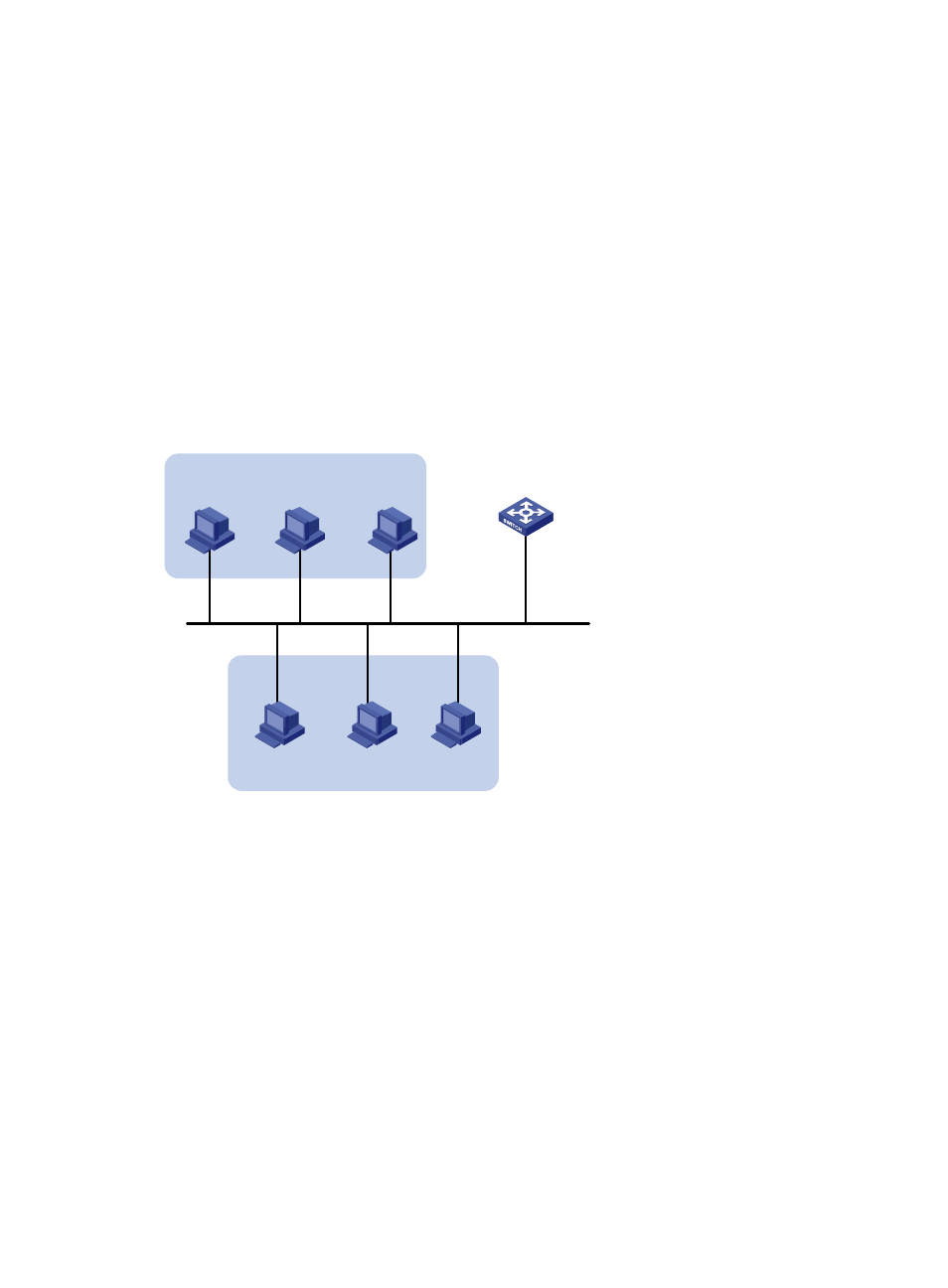
As shown in
, a port in VLAN 1 on a switch is connected to a LAN comprising two segments:
172.16.1.0/24 and 172.16.2.0/24.
To enable the hosts on the two network segments to communicate with the external network through the
switch, and to enable the hosts on the LAN to communicate with each other:
•
Assign a primary IP address and a secondary IP address to VLAN-interface 1 on the switch.
•
Set the primary IP address of the switch as the gateway address of the PCs on subnet 172.16.1.0/24,
and set the secondary IP address of the switch as the gateway address of the PCs on subnet
172.16.2.0/24.
Figure 8 Network diagram
Configuration procedure
# Assign a primary IP address and a secondary IP address to VLAN-interface 1.
<Switch> system-view
[Switch] interface vlan-interface 1
[Switch-Vlan-interface1] ip address 172.16.1.1 255.255.255.0
[Switch-Vlan-interface1] ip address 172.16.2.1 255.255.255.0 sub
# Set the gateway address to 172.16.1.1 on the PCs attached to subnet 172.16.1.0/24, and to 172.16.2.1
on the PCs attached to subnet 172.16.2.0/24.
Verifying the configuration
# Ping a host on subnet 172.16.1.0/24 from the switch to check the connectivity.
<Switch> ping 172.16.1.2
Vlan-int1
172.16.1.1/24
172.16.2.1/24 sub
172.16.1.0/24
172.16.1.2/24
172.16.2.0/24
172.16.2.2/24
Host A
Host B
Switch