Configuration procedure – H3C Technologies H3C S12500-X Series Switches User Manual
Page 181
170
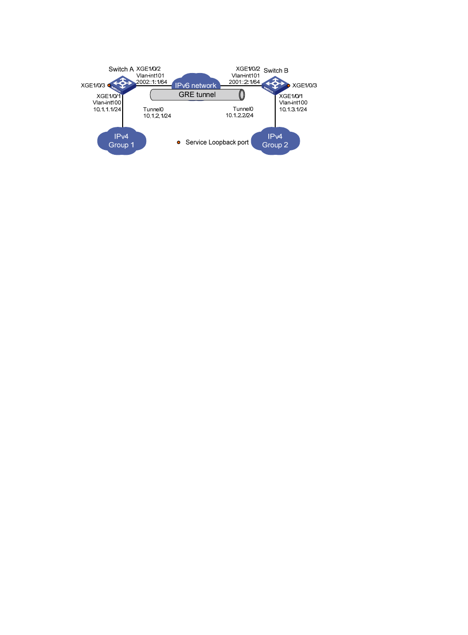
Figure 64 Network diagram
Configuration procedure
Before the following configurations, configure an IP address for each interface, and make sure Switch A
and Switch B can reach each other.
1.
Configure Switch A:
# Create service loopback group 1, and configure the service type as tunnel.
<SwitchA> system-view
[SwitchA] service-loopback group 1 type tunnel
# Add port Ten-GigabitEthernet 1/0/3 to service loopback group 1.
[SwitchA] interface Ten-GigabitEthernet 1/0/3
[SwitchA-Ten-GigabitEthernet1/0/3] port service-loopback group 1
[SwitchA-Ten-GigabitEthernet1/0/3] quit
# Create a tunnel interface Tunnel 0, and specify the tunnel mode as GRE over IPv6.
[SwitchA] interface tunnel 0 mode gre ipv6
# Configure an IP address for the tunnel interface.
[SwitchA-Tunnel0] ip address 10.1.2.1 255.255.255.0
# Configure the source address of the tunnel interface as the IPv6 address of VLAN-interface 101
on Switch A.
[SwitchA-Tunnel0] source 2002::1:1
# Configure the destination address of the tunnel interface as the IPv6 address of VLAN-interface
101 on Switch B.
[SwitchA-Tunnel0] destination 2001::2:1
[SwitchA-Tunnel0] quit
# Configure a static route from Switch A through the tunnel interface to Group 2.
[SwitchA] ip route-static 10.1.3.0 255.255.255.0 tunnel 0
2.
Configure Switch B:
# Create service loopback group 1, and configure the service type as tunnel.
<SwitchB> system-view
[SwitchB] service-loopback group 1 type tunnel
# Add port Ten-GigabitEthernet 1/0/3 to service loopback group 1.
[SwitchB] interface Ten-GigabitEthernet 1/0/3
[SwitchB-Ten-GigabitEthernet1/0/3] port service-loopback group 1
[SwitchB-Ten-GigabitEthernet1/0/3] quit
# Create a tunnel interface Tunnel 0, and specify the tunnel mode as GRE over IPv6.
[SwitchB] interface tunnel 0 mode gre ipv6