Basic concepts, Operation mode, Role – H3C Technologies H3C S7500E Series Switches User Manual
Page 10
1-3
Basic Concepts
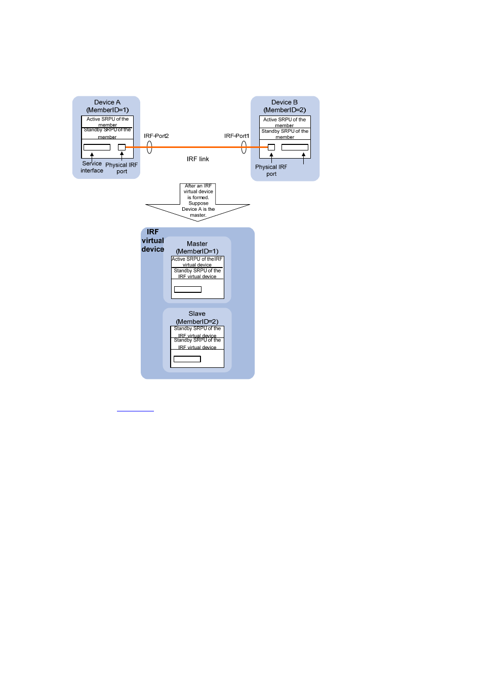
Figure 1-2 IRF implementation schematic diagram
As shown in
, Device A and Device B are physically connected. After you perform necessary
configurations on them, they form an IRF virtual device, which has four switching and routing
processing units (SRPUs) (one active SRPU and three standby SRPUs) and two interface cards. The
IRF virtual device manages both the physical and software resources of Device A and Device B.
The IRF technology involves the following basic concepts:
Operation mode
The device can operate in either of the following two modes:
z
Standalone mode: The device operates in a standalone manner. It cannot form any IRF virtual
device with other devices.
z
IRF mode: The device can connect with other devices to form an IRF virtual device.
You can switch the operating mode of the device at the command line interface (CLI).
Role
The devices that form an IRF virtual device are called member devices. Each of them plays either of the
following two roles:
z
Master: Manages the IRF virtual device.
z
Slave: All members that operate as the backups of the master are called slaves. When the master
fails, the IRF virtual device automatically elects a new master from one of the slaves.