Installing pc, Jupiter lan – Grass Valley VM 3000 System Controllers v.7.4 User Manual
Page 115
Hardware Installation
2−43
VM 3000 Installation and Operating Manual
Installing PC
Minimum hardware and software requirements have already been described (page 1−6).
Follow the instructions supplied with the file server for connection of monitor, keyboard, and mouse.
JUPITER LAN
Jupiter file server(s) are connected to the VM 3000 through an IP hub, switch, or media converter via the “Jupiter LAN.”
The portion of the Jupiter LAN connected directly to the file server is an IEEE 802.3 10/100BaseT network using a twisted
pair cable with RJ−45 connectors (Cat 5E Enhanced is recommended). Shielded cable is also recommended, maximum length
60 meters. Compliance with EEC, EMC, EN series, UL− 1950, and CSA C22.2 No. 950−M89 standards requires use of a
shielded cable. Maximum length for unshielded cable is 100 meters.
Note: Other than IP devices such as hubs, connection of non−Jupiter equipment to the Jupiter LAN is not recom-
mended and will not be supported.
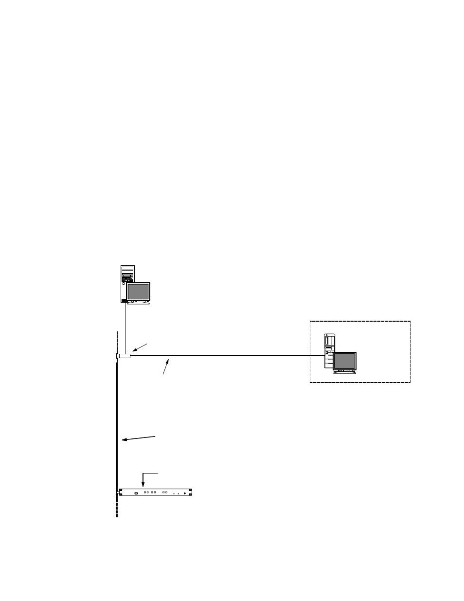
Jupiter File Server
10Base2 LAN cable (for
cable details see page
2−46.)
Figure 2−52. PC−to−VM connections..
“Remote”
PC
with
LAN−3000
LAN
board
(see page
2−45)
Media
converter/
switch
ÎÎ
ÎÎ
ÎÎ
ÎÎ
Î
ÎÎ
ÎÎ
ÎÎ
ÎÎ
ÎÎ
Î
Î
Î
ÎÎ
ÎÎ
Î
Î
ÎÎ
ÎÎ
ÎÎ
Î
Î
ÎÎ
Î
Î
Î
Î
Î
Î
Î
Î
Î
Î
ÎÎ
ÎÎ
ÎÎ
ÎÎÎ
ÎÎÎ
ÎÎÎ
ÎÎÎ
ÎÎÎ
Î
Î
Î
ÎÎ
Î
Î
Î
ÎÎÎ
ÎÎÎ
ÎÎÎ
ÎÎÎ
10/100baseT
LAN
ÎÎÎ
ÎÎÎ
ÎÎÎ
ÎÎÎ
ÎÎÎ
Î
Î
Î
ÎÎ
Î
ÎÎ
Î
ÎÎÎ
ÎÎÎ
ÎÎÎ
ÎÎÎ
VM 3000
System
Controller
“Device” internal rotary
switches set to “00.” See
Figure 2−53.
The VM 3000 internal “Device” switches must be set to “00.” See Figure 2−52.