Grass Valley VM 3000 System Controllers v.7.4 User Manual
Page 252
Configurator
Switcher Description Table
5−42
VM 3000 Installation and Operating Manual
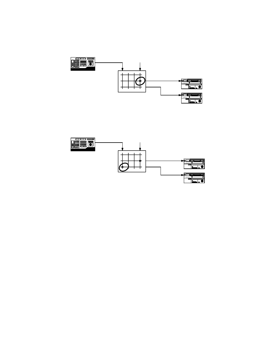
When “Enforce” is turned on, and an attempt is made to switch control to a new device, then the device presently being con-
trolled will be switched automatically to a “safe” (non−existent) input (Figure 5−25).
Figure 5−25.
Editor
VCR 1
VCR 2
“Safe input”
Controller level
The control device would then be switched to the new destination (Figure 5−26).
Figure 5−26.
Editor
VCR 1
VCR 2
“Safe input”
Controller level
— For Venus DM 400/400A data routers, the Safe Input is defined as the first input listed on the Switcher Input
table (page 5−48), which is the same as “logical input 1.” The physical input number of the Safe Input
should always be “192;” this insures that the router will tri−state (i.e., the destination will be connected to a
high−impedance source).
— For DM 400B data routers, the Safe Input is defined as whatever input is named “SAFE” on the Switcher
Input table (page 5−48); the physical input number should always be one (1) beyond the last input number
(e.g., if the inputs are numbered 000−063, then the Safe Input would be 064). In these systems selecting the
Safe Input will cause the destination to be switched “off.”
When “Advise” is turned on and an attempt is made to switch control to a new device, the switch will not occur. The system
will display the following message on the control panel:
Input currently in use by <output number>
The operator can then switch the “safe input” to the device presently being controlled. This will avoid having the control de-
vice connected to two machines at the same time.
When “Normal” is turned on and an attempt is made to switch control to a new device, the switch will occur immediately.
There will be no notification of conflict or extra switch to a safe input.