Figure 5−131 – Grass Valley VM 3000 System Controllers v.7.4 User Manual
Page 363
Configurator
Machine Control Table
5−153
VM 3000 Installation and Operating Manual
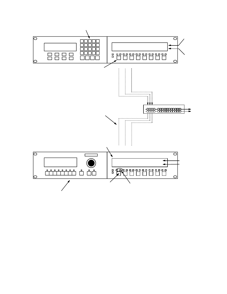
CP 3000
Switcher control
Expansion panel
MC 3000
Machine control
Expansion panel
SELECT source
TAKE to
destination
CONTROL all functions of machine
selected by expansion panel
Production switcher
A B C
A
B
C
VT01
PrdA
VC01
PrdB
Identifies machines selected as
sources for production switcher
A
B
C
START and
STOP machine
SELECT machine
to be controlled by
MC 3000. Note as-
terisk next to ma-
chine name
Machine control linkage
follows routing switcher
VC02
PrdC
STOP
VC01
STOP
VC02
Switcher input name
Switcher output nam
Status
Machine name
STOP
:
VT01
CAT=VTR SELECT=VT01
VT01 VT01 VT01 VT01
00:54:49:11 T1
VT01 STOP MAN
Figure 5−131. Example of automatic machine linkage sequence. Please see page 5−152 for discussion.
[1]
[2]
[3]
[4]
[5]