Appendix f, Esbus" specifications, Esbus” specifications – Grass Valley VM 3000 System Controllers v.7.4 User Manual
Page 667: Mechanical and electrical characteristics, Specification (appendix f)
Advertising
F−1
VM 3000 Installation and Operating Manual
Appendix F
“ESbus” Specifications
MECHANICAL AND ELECTRICAL CHARACTERISTICS
Source: EBU tech. 3245−E, Remote−Control Systems for Television Equipment, December, 1984.
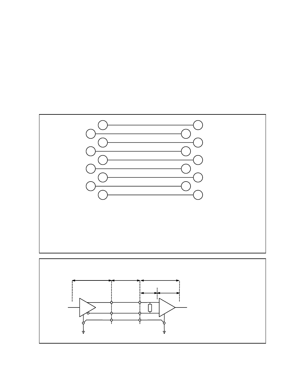
Figure F−1. Connector pin assignment.
FG
1
RC
6
RA
2
RB
7
TB
3
TA
8
TC
4
FG
9
SP
5
FG
1
TC
6
TA
2
TB
7
RB
3
RA
8
RC
4
FG
9
SP
5
Bus controller
Tributary
FG
Frame ground
TA
Transmit “A”
TB
Transmit “B”
TC
Transmit−signal common
RA
Receive “A”
RB
Receive “B”
RC
Receive−signal common
SP
Spare
A < B ”MARK” state
A > B ”SPACE” state
G
R
Generator
Balanced
Interconnecting
Cable
Load
Receiver
R
t
+
−
1 = HI
0 = LO
1 = HI
0 = LO
B
TB
A
TA
C
TC
RB
B’
RA
A’
RC
C’
Cable
termination
Figure F−2. Balanced digi-
tal interface circuit.
Advertising
This manual is related to the following products: