Ab c d, F4 f3 f2 f1 – Grass Valley VM 3000 System Controllers v.7.4 User Manual
Page 127
Hardware Installation
2−55
VM 3000 Installation and Operating Manual
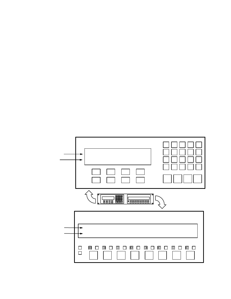
CP 3000 Switcher Control Panel and CP 3010 Expansion Panel
Installation of these panels is shown on page 2−50.
The basic control panel, referred to as the CP 3000, can be configured for single−bus operation (allowing selection of a source
for one destination), multi−bus operation (allowing selection of a source for several destinations), or full matrix operation
(selection of a source for any destination). This panel can be arranged to select one of 20 source categories (VTR, CAM, etc.)
and then, using a 10−key pad, a unit within the category. Crosspoint status is provided by the display window. Additional push
buttons provide breakaway (control of individual switcher levels such as left audio, time code, etc), chop, lock, protect, and
override switching. A password can be assigned to the panel if desired.
The CP 3000 can also be operated in connection with an adjacent CP 3010 expansion panel (see Figure 2−65). For multi−bus
control the desired source can be selected on the CP 3000; the CP 3010 would then display the names of eight destinations,
beneath which are eight corresponding TAKE keys; one of these would be pressed to complete the switch. The page of eight
destinations can be scrolled to display up to 160 possible destinations. A blank panel is supplied when the CP 3000 is mounted
without a CP 3010.
Note: The original version of the CP 3000 panel can now be retrofitted in the field with re−legendable keys, using
the CP 3000RBK Relegendable Button Kit, part no. 44−046025−001.
The CP 3000/3010 panels are configured using the MPK Devices table (page 5−109).
For operating instructions, see page 6−7.
∨
∧
>
>
>
>
>
>
>
>
TAKE
———
SEL
TAKE
———
SEL
TAKE
———
SEL
TAKE
———
SEL
TAKE
———
SEL
TAKE
———
SEL
TAKE
———
SEL
TAKE
———
SEL
Figure 2−64. CP 3000
Switcher control panel with
example display.
Status for 4 levels
Overrides
VTR1 VT1L VT1R VT1T
BLK BARS VTR1 VTR2
Figure 2−65. CP 3010 Ex-
pansion panel.
Status
CAM1 CAM3 CAM2 VTR1
MON1 MON3 MON2 VTR2
Output
VTR
1
CG
2
NET
3
SAT
EJ
VCR
4
CAM
5
REM
6
FILM
7
PTCH
8
STU
9
FS
AUX
TEST
0
MISC
SS
A
B
C
D
TAKE
CHOP
LOCK
PROT
F4
F3
F2
F1
MORE
CLR
MENU
LEV