Appendix a connector pin-outs – Grass Valley PDR 200 Service Manual User Manual
Page 158
Advertising
Appendix A Connector Pin-outs
A-2
PDR 200 Installation Manual
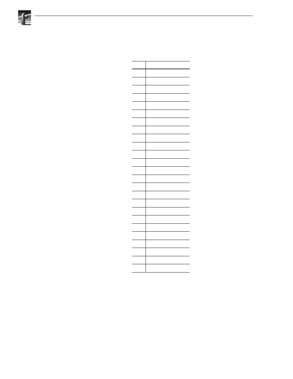
Table A-2 lists the pin-outs for the Parallel Port connector on the S-VGA board.
Table A-2. SVGA Board Parallel Port Connector Pin-outs
Pin
Signal
1
STROBE/
2
PD(0)
3
PD(1)
4
PD(2)
5
PD(3)
6
PD(4)
7
PD(5)
8
PD(6)
9
PD(7)
10
ACK
11
BUSY
12
PAPER ERROR
13
SLCT
14
AUTO FEED
15
ERROR
16
INIT
17
SLCTIN/
18
GND
19
GND
20
GND
21
GND
22
GND
23
GND
24
GND
25
GND
Advertising