Instructions on installation, 2 mechanical installation – Yaskawa CIMR-LU Drives User Manual
Page 19
2 Mechanical Installation
YASKAWA ELECTRIC TOEP C710616 38F YASKAWA AC Drive L1000A Quick Start Guide
19
Mec
h
an
ic
al
In
st
al
lat
io
n
2
■
Instructions on Installation
Eye bolts are used to install the drive or to temporarily lift the drive when replacing it. The drive can be installed in an
enclosure panel or on a wall. Do not leave the drive suspended by the wires in a horizontal or vertical position for long
periods of time. Do not transport the drive over long distances. Read the following precautions and instructions before
installing the drives.
WARNING! Be sure to observe the following instructions and precautions. Failure to comply could result in minor or moderate injury
and damage to the drive from falling equipment.
• Before using wires to suspend the drive vertically and horizontally, make sure that the drive front cover,
terminal blocks and other drive components are securely fixed with screws.
• Do not subject the drive to vibration or impact greater than 1.96 m/s
2
(0.2 G) while it is suspended by the
wires.
• Do not overturn the drive while it is suspended by the wires.
• Do not leave the drive suspended by the wires for long periods of time.
Horizontal Suspension of the Drive (CIMR-LU2A0346, 2A0415, 4A0216 to 4A0605, and 5A0172 to 5A0200)
To make a wire hanger or frame for use when lifting the drive with a crane, lay the drive in a horizontal position and pass
a wire through the holes of the four eye bolts.
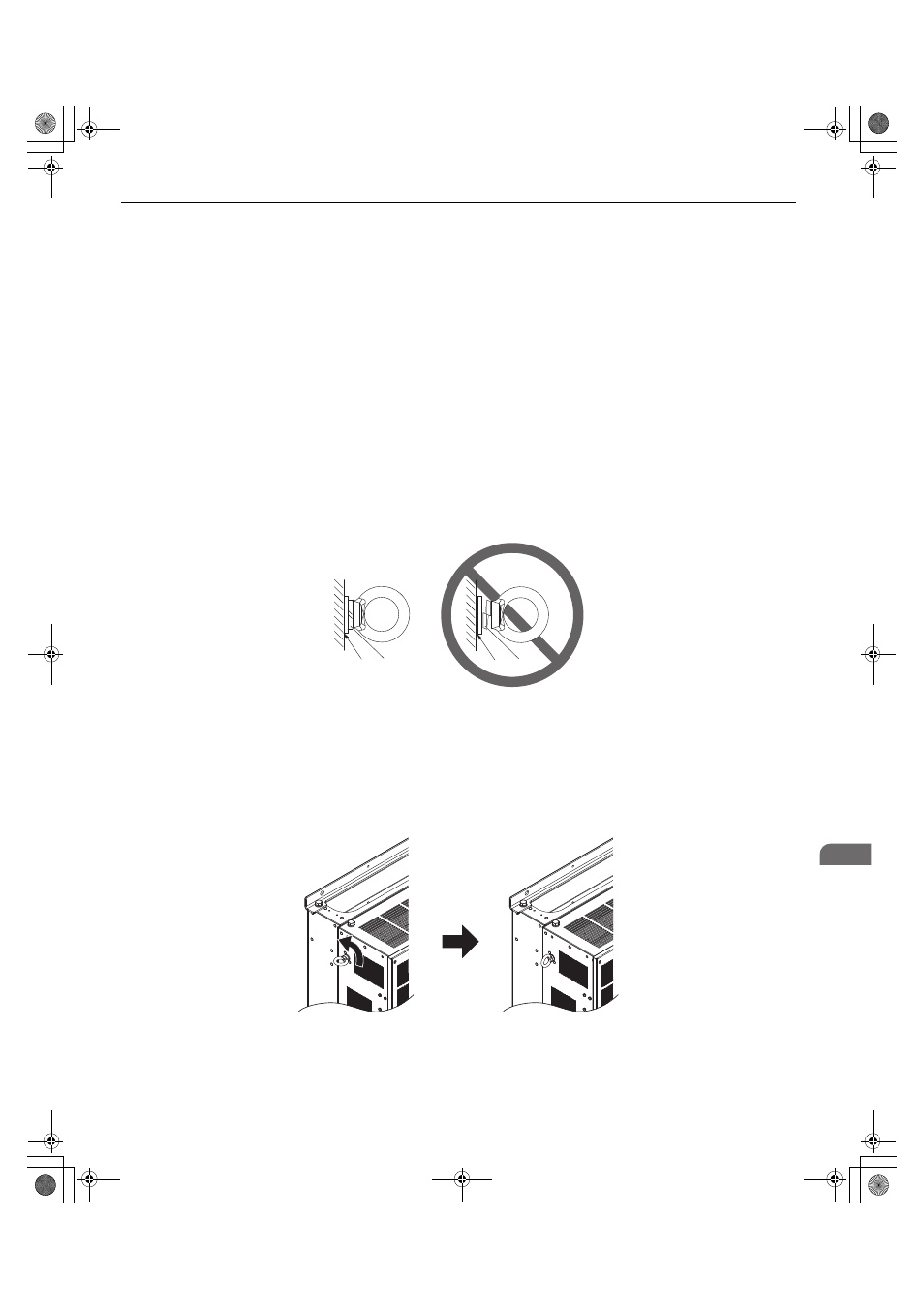
When lifting the drive, confirm that the spring washer is fully closed. If not, the drive may become deformed or damaged
when lifted.
Figure 7
Figure 6 Details of Spring Washers
Vertical Suspension of the Drive (CIMR-LU2A0346, 2A0415, 4A0216 to 4A0605, and 5A0172 to 5A0200)
When vertical suspension of the drive is required in an enclosure panel, the orientation of the eye bolts for these drive
models can be easily changed by turning the eye bolts counterclockwise 90 degrees.
Figure 8
Figure 7 Adjusting Angle of Eye Bolts (CIMR-LU2A0346, 2A0415, 4A0216 to 4A0605, and 5A0172 to 5A0200)
A – No space between drive and washer
C – Space between drive and washer
B – Spring washer: Fully closed
D – Spring washer: Open
B
A
C
D
TOEP_C710616_38F_5_0.book 19 ページ 2013年12月4日 水曜日 午前9時56分