Terminal configuration, Yea_common – Yaskawa CIMR-LU Drives User Manual
Page 49
3 Electrical Installation
YASKAWA ELECTRIC TOEP C710616 38F YASKAWA AC Drive L1000A Quick Start Guide
49
El
ec
tr
ical
I
n
st
al
lat
io
n
3
■
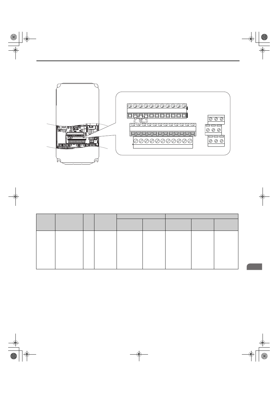
Terminal Configuration
Control circuit terminals are arranged as shown in
Figure 26
Figure 26 Control Circuit Terminal Arrangement
Wire Size and Torque Specifications
WARNING! Fire hazard. Tighten all terminal screws to the specified tightening torque. Loose electrical connections could result in
death or serious injury by fire due to overheating of electrical connections. Improperly tightened terminal screws can also cause
erroneous equipment operation.
Select appropriate wire type and gauges from
. For simpler and more reliable wiring, use crimp ferrules on the
wire ends. Refer to
for ferrule terminal types and sizes.
Table 17 Wire Gauges and Torque Specifications
Terminal
Block
Terminal
Size
Tightening
Torque
N m
(lb.in.)
Bare Wire Terminal
Ferrule-Type Terminal
Applicable
Wire Size
mm
2
(AWG)
Recomm.
mm
2
(AWG)
Applicable
Wire Size
mm
2
(AWG)
Recomm.
mm
2
(AWG)
Wire Type
TB1, TB2,
TB4, TB5,
TB6
FM, AC, AM, P1,
P2, PC, SC, A1,
A2, A3, +V, -V,
S1-S8, MA, MB,
MC, M1, M2, HC,
H1, H2, DM+,
DM-, IG, R+, R-,
S+, S-, RP, MP, E
(G)
M2
0.22 to 0.25
(1.9 to 2.2)
Standard wire:
0.25 to 1.0
(24 to 17)
Solid wire:
0.25 to 1.5
(24 to 16)
0.75
(18)
0.25 to 0.5
(24 to 20)
0.5
(20)
Shielded wire,
etc.
E(G) HC H1
H2 DM+ DM- IG
R+
R-
S+
S-
S1
S2
S3
S4
S5
S6
S7
S8
SN SC SP
V+ AC
V-
A1
A2 FM AM AC
P1
C1
C2
P2
M3 M4
M6
MA MB MC
M1 M2 M5
YEA_common
TOEP_C710616_38F_5_0.book 49 ページ 2013年12月4日 水曜日 午前9時56分