Structure of motion program alarms, Structure of motion program alarms -5 – Yaskawa MP3200 Troubleshooting Manual User Manual
Page 80
5.1 Troubleshooting Motion Program Alarms
Structure of Motion Program Alarms
5-5
T
roubleshooting Programming and Debugging
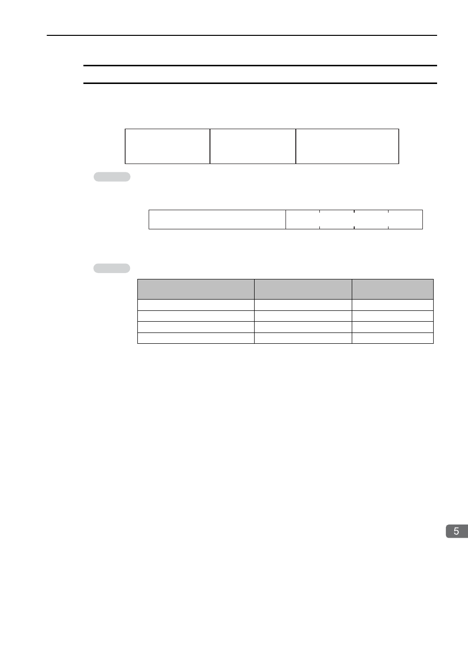
Structure of Motion Program Alarms
You can monitor for motion program alarms in the SL26000 to SL26510 system registers.
The structure of the motion program alarm data stored in the system registers is shown below.
You can also monitor for motion program alarms in the SW03268 system registers.
The structure of the motion program alarm data stored in the SW03268 system register is shown
below.
Note: The system register addresses depend on the system work number. Refer to the fol-
lowing section for details.
Alarm Indications
Alarm Axis (Camera)
Information
(1 to 32)
Circuit Information
(1 to 32)
Bit 1F
Bit 18
Bit 17
Bit 10
Bit F
Bit 0
Alarm Code
Program alarm: 0
hex
Axis alarm: 1
hex
Vision alarm: 4
hex
Information
Alarm Axis Information (1 to 32)
Bit F
Bit 8
Bit 7
Bit 0
Alarm Code (Axis alarm when bit 7 is ON.)
Example
Alarm (Example)
Expansion Motion Program
Alarm
Motion Program Alarm
Program Alarm
000000 hex
00 hex
Circuit 2 Axis 3 Axis Alarm
020310 hex
03 hex
Circuit 2 Camera 3 Vision Alarm
02034 hex
037F hex
Circuit 2 Vision Alarm
02004 hex
007F hex