Natural convection (vn), Forced convection (vf), Release of counterweights – MCZ AirSystem 70 DX User Manual
Page 17
Chapter 4
INSTALLATION AND USE MANUAL
page
17
Installation and assembly
Technical service – MCZ S.p.A. all rights reserved - Reproduction prohibited
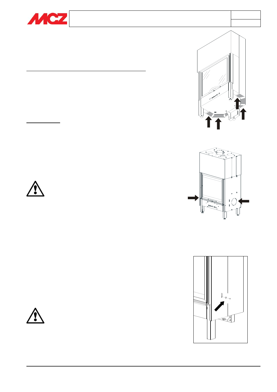
4.2.1. Natural convection (VN)
If you adopt this system, the knockout panels in the lower part of
the stove body must be removed in order to facilitate heat exchange
and air circulation.
Airsystem line with the exception of Airsystem B70
In all models of the Airsystem line, except for model B70, the knockout
panels are located under the bottom of the unit as shown in
figure 1.
The sum of the sections of the knockout panels is equal to the section
of the two upper cut-outs for the ducting of hot air. Therefore, by
opening all the knockout panels, it is possible to duct two upper outlets.
If you decide to use this method of ventilation, it is not advisable to
duct more than two nozzles to prevent air dispersion in the tubes.
Airsystem B70
Differently from all the other models, the Airsystem B70, for reasons of
construction, does not have knockout panels on the bottom; instead,
they are located on the steel sides. The cut-outs are circular in shape,
Ø 150 mm. They should both be opened if you want to duct the two
nozzles for the distribution of hot convection air
(figure 2).
To open the knockouts, whether they are on the sides or under the
unit, hit them with a rubber mallet and remove the profile that
detaches from the unit.
ATTENTION!
With the fireplace stove thus prepared (knockout
panels removed), it is NOT ADVISABLE to install the
forced ventilation kit afterwards.
4.2.2. Forced convection (VF)
If you implement this system, you must not remove the knockout
panels located on the bottom or side of the unit and purchase the
FORCED VENTILATION KIT 180-480-620 m
3
/h optional.
Then proceed accordingly when specified in
paragraph 4.8 “Installation
of forced ventilation kit".
4.3. RELEASE OF COUNTERWEIGHTS
The fireplace stove is delivered with the sliding counterweights locked
in place. In this way, during shipping and handling, they will not strike
and damage the sliding parts, the door and the ceramic glass.
To release the counterweights and therefore also the door, remove the
screws as shown in
figure 3 from both sides of the fireplace stove.
Remove the screws that hold the counterweights
only after you have positioned the fireplace stove
and to ensure that the glass is in good condition.
DO NOT MOVE THE FIREPLACE STOVE WITHOUT THE
SCREWS THAT HOLD THE COUNTERWEIGHTS.
Damage caused by failure to observe this rule is the
responsibility of the client or his representative.
Figure 1 – Airsystem line knockout panels
Figure 2 – Airsystem B70 knockout panels
Figure 3 – Screw to hold counterweights