MCZ AirSystem 70 DX User Manual
Page 24
Chapter 4
INSTALLATION AND USE MANUAL
page
24
Installation and assembly
Technical service – MCZ S.p.A. all rights reserved - Reproduction prohibited
•
Before putting the hermetic bottom C back in place, make the
electrical connections as shown in the following paragraph.
•
Once the electrical connections are complete, put the hermetic
bottom C back in place and secure it with the self-tapping screws
B
(figure 14)
•
Re-insert the fire beds, the drawer and the ash grille
Make sure that the removable bottom C is
hermetically sealed and that the gaskets mounted on
the bottom are in good shape.
4.9. CONNECTION OF CONTROL UNITS AND
PROBES
All wiring must be carried out with the electrical
sockets disconnected. Make sure that the electrical
sockets are grounded.
4.9.1. Control unit FC715 and probe installation
Arrange in advance for the connections of the control unit FC715 as
shown in
diagram 1 of page 29 if you are installing a kit of 480-620
m
3
/h
or as in diagram 2 on page 30 if you are installing a kit of
180m
3
/h.
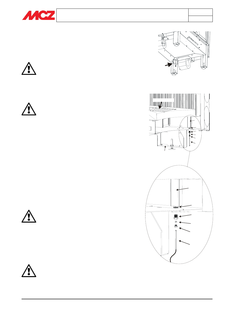
PROBE INSTALLATION:
•
Screw in without tightening completely the screw that holds
the probe G to the probe support E, placing in between the bush
F
(figure 16).
•
Screw in the entire probe support E+F+G in the hole D (size 10
wrench)
•
Insert probe H all the way into the hole of the screw that holds
probe G and gently tighten the screw G (size 7 wrench).
•
The probe will be inserted in the upright of the fireplace stove C.
Once the connection is complete and the plug placed in the socket of
the home, check that the red LED on the control unit lights up.
All wiring must be carried out with the electrical
sockets disconnected. Make sure that the electrical
sockets are grounded.
4.9.2. Positioning of control unit and FC715
The control unit must be placed on the floor, behind or alongside the
fireplace stove, in a zone that is accessible for maintenance and above
all far from the bottom of the structure as shown in
figure 17.
Make sure that the control unit does not come into hot metallic parts of
the fireplace stove, as it can be damaged by heat.
The equipment must be powered at 220V at 50Hz.
Correct connection to the earth system is vital.
Make sure that the cables do not come into contact with the
metal parts of the structure, as they get extremely hot.
Figure 14 – Installation of bracket with terminal
board
Piedino posteriore
Sezione del piano fuoco
Griglia cenere
Cassetto
cenere
E
F
G
H
D
C
E
F
G
H
D
C
Figure 16 – Probe installation
F