Forced ventilation kit 180 m, H (only b70) – MCZ AirSystem 70 DX User Manual
Page 23
Chapter 4
INSTALLATION AND USE MANUAL
page
23
Installation and assembly
Technical service – MCZ S.p.A. all rights reserved - Reproduction prohibited
Asola
IMPORTANT!
PRIOR TO INSTALLATION, ENSURE THAT THE
KNOCKOUT PANELS LOCATED ON THE BOTTOM OF
THE FIREPLACE STOVE HAVE NOT BEEN REMOVED.
IF THE KNOCKOUT PANELS HAVE BEEN REMOVED
(SEE PAGE 25), YOU WILL NEED TO PUT THEM BACK
OR CLOSE OFF THE HOLES WITH STEEL PLATES.
4.8.3. Forced ventilation kit 480-620 m
3
/h
For the installation of the forced ventilation kit of 480-620 m
3
/h,
proceed as follows:
• Raise the door of the fire box
• Remove the cast iron grille, the ash drawer and the two semi-
tops in white refractory material (Alutec®)
• Unscrew the self-tapping screws B and remove the hermetic
bottom C
(figure 10)
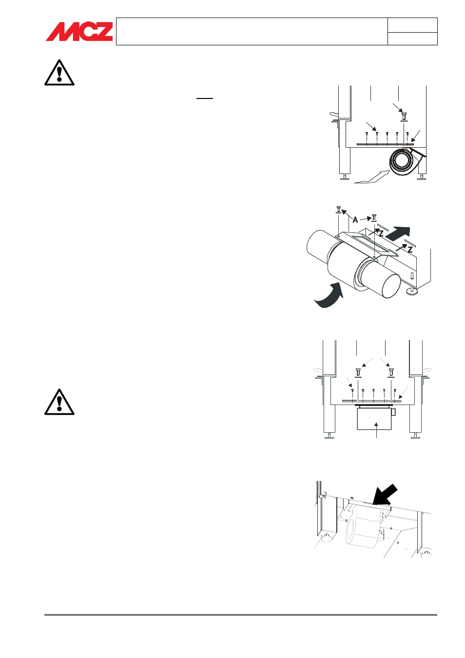
• Insert the electric fan kit 480 or 620 m
3
/h complete with
fastening flange facing as shown in
figure 11, so that the two
inserts of the flange fit into the slots Z of the back foot.
• Raise the fan block as in figure 11 so as to match the holes of
the flange with those of the bottom of the fireplace stove.
• Lock all in place by tightening the two screws A, from above
the back, so as to secure the fan 480-620 m
3
/h to the frame
(figure 10).
• Before putting the hermetic bottom C back in place, make the
electrical connections as shown in the following paragraph.
• Once the electrical connections are complete, put the hermetic
bottom C back in place and secure it with the self-tapping
screws B
(figure 10)
Make sure that the removable bottom C is
hermetically sealed and that the gaskets mounted on
the bottom are in good shape.
4.8.4. Forced ventilation kit 180 m
3
/h (only B70)
For the installation of the forced ventilation kit of 180 m
3
/h, proceed as
follows:
•
Raise the door of the fire box
•
Remove the cast iron grille, the ash drawer and the two semi-
tops in white refractory material (Alutec®)
•
Unscrew the self-tapping screws B and remove the hermetic
bottom C
(figure 12)
•
Insert the fans of 180 m
3
/h, facing as in
figure 13, so that the
insert on the flange of the fan enters the slot on the structure of
the fireplace stove
(figure 13).
•
Secure the fans to the frame by tightening the two screws A
from above the back
(figure 12)
•
Fasten the steel bracket with the terminal board for electrical
wiring with the self-tapping screw F provided
(figure 14).
Figure 11 – Fan position 480-620 m3/h
Figure 10 – Disassembly of internal fire bed
Figure 13 – Fan installation
Figure 12 – Disassembly of internal fire bed
A
B
C
A
B
C