MCZ AirSystem 70 DX User Manual
Page 21
Chapter 4
INSTALLATION AND USE MANUAL
page
21
Installation and assembly
Technical service – MCZ S.p.A. all rights reserved - Reproduction prohibited
4.8. INSTALLATION OF FORCED VENTILATION KIT
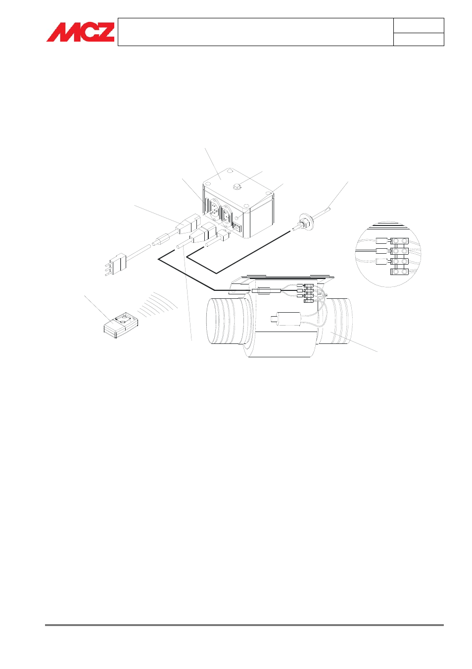
4.8.1. Components of kit VF 480-620 m
3
/h with control unit FC715 (Airsystem
line)
FUSE
ACOUSTIC SIGNAL EMITTER
LINE SIGNAL
LED
1
2
3
4
5
6
Yellow-green
Brown
Blue
Diagram 1 – Wiring Kit VF for Airsystem (not including Airsystem B70) with control unit FC 715
1. Radio remote control complete with internal battery
2. Fan cable with plug and terminals
3. Supply cable with plug and socket
4. Power supply device with built-in radio receiver
5. Fan 480-620 m³/h
6. Silicon probe cable with snap-in connection
complete with electronic probe (for control unit
mod. FC715)