MCZ Comfort Air SLIM User Manual
Page 22
SLIM-BASIC COMFORT AIR KIT
Chapter 3
USE AND MAINTENANCE MANUAL
page
22
Basic comfort air kit
Technical dept. - All rights reserved by MCZ Group S.p.A. - Reproduction prohibited
2.3.2.
Positioning the electronic control unit
Prepare the recessed box “A” for the control unit installation, making
sure you position it as far away as possible from the heat source,
taking into account the length of the cables supplied in the kit and of
the temperature sensor, if any.
Thread all the cables (power supply, ventilation and actuator) through
the recessed box “A” so they are available for the connection. Connect
them to the terminals on the control unit (B) as explained in the
paragraph below.
Once the connections have been made, insert the control unit body and
secure it to the recessed box “A” using the screws provided.
Next, insert the plate provided “E”.
The control unit body is designed to house AVE plates from the
SISTEMA 45 range and VIMAR plates from the IDEA range, of various
colours and easily available for purchase.
We advise you install the control unit on the wall as far away
as possible from the heat source.
If the control unit cannot be secured to the wall, the motor support can
be used, in which case it is preferable to leave the flap open to allow
the control unit to cool down and have a visual indication of the
ventilation speed set.
Inserting the control unit into the motor support
Follow the instructions below to insert the control unit into the
motor support:
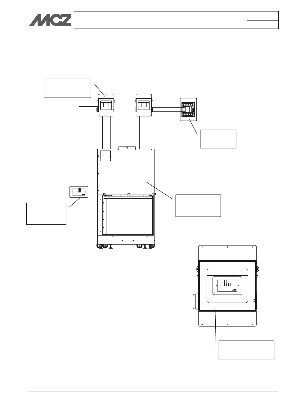
CONTROL
UNIT
HOT AIR
OUTLET
FAN KIT
CLOSED
FIREPLACE
Control unit secured
to the motor support