Mcz control unit connection, The control unit mcz – MCZ Hydrotherm 70 User Manual
Page 19
INSTALLATION AND USE MANUAL
Chapter 4
page
19
Installation and assembly
Technical service – MCZ GROUP S.p.A. all rights reserved - Reproduction prohibited
4.5. MCZ CONTROL UNIT CONNECTION
MCZ shall not be held liable for any damage to
persons or objects due to incorrect connections or
improper use of the device.
The Hydrotherm fireplace stove must be managed by a control unit
fitted with temperature probe, to manage the activation of the pump
and the acoustic signal warning that the safety temperature has been
exceeded.
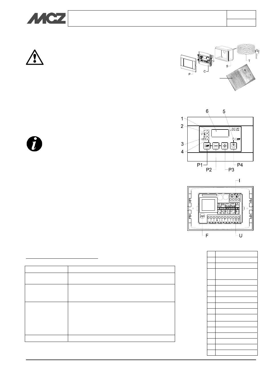
The MCZ control unit consists of:
Recessed box (S).
Temperature probe (T).
Cover plate (P).
Control unit body (C)
Instruction sheet (K).
The control panel must be installed far from heat
sources and in a way that the length of the cables
provided is sufficient.
The box must not be installed on the hood of the
cladding.
The cables must not remain in contact with the metal
structure.
When installing the control panel, a 230Vac-50Hz power supply cable
must be provided.
4.5.1. The control unit MCZ
The thermal adjuster has the task of:
Detecting, measuring and displaying the temperature of the
boiler.
Control the control devices in the system.
Signal when the boiler exceeds the safety temperature through
an acoustic and luminous signal.
TECHNICAL CHARACTERISTICS
Power supply:
230 Vac
10%~ 50 Hz; Protection fuse T3,15 A
Power
consumption:
2VA~
Temperature
probe:
In silicone/pvc cable
Operating temperature: -50°C / 130 °C
Measure limits: 0 – 99 °C
Precision:
1°C
Outputs:
PUMP output:
powered at 230 Vac - max flow 5A - 250 Vac
VALV output:
free contact - max flow 5A - 250 Vac
AUX output:
free contact - max flow 5A - 250 Vac
Dimensions:
Recessed thermal adjuster: 120 x 80 x 50 [mm]
P Cover
plate
C Control
unit
S Recessed
box
T Temperature
probe
I Inputs
U Outputs
F Fuse
P1 MENU button
P2 Increase button
P3 Increase button
P4 ON/OFF button
1 Pump LED 1
2 3-way valve LED
3 Pump LED 2
4 Auxiliary
LED
5 ON/OFF
LED
6 Display
K