Installation – MCZ Hydrotherm 70 User Manual
Page 31
INSTALLATION AND USE MANUAL
Chapter 4
page
31
Installation and assembly
Technical service – MCZ GROUP S.p.A. all rights reserved - Reproduction prohibited
Materials: - body
Brass EN 12165 CW617N
- control spindle
Brass EN 12164 CW614N
- obturator seal
EPDM
- seals
EPDM
- spring
Stainless steel
- protection cover
POM
Max. working pressure
10 bar
Set temperature
95°C
Temperature range
5÷110°C
Discharge flowrate at 110°C and ∆p 1 bar
3000 l/h
Ambient temperature range
0÷80°C
Action type (EN 14597)
2 KP
Max temperature of the sensor
130°C
Medium water
PED category
IV
Connections
3/4” F x 3/4” F
Probe connection
1/2” M
Capillary lenght
1300 mm
4.8.3. Installation
Before installing the thermal safety discharge valve, ensure that the
system has no impurities that may be deposited on the outlet housing.
An easy-to-open filter should be installed on the arrival of cold water
and its cleaning should be regularly checked. Upon reaching the
temperature of 95°C, the valve starts to discharge the quantity of water
necessary to maintain the temperature of the boiler within the safety
limits.
Check that the valve's discharge capacity is compatible with the limit
values indicated by the manufacturer of the boiler and the system. For
safety reasons, any cut-off valves placed upstream of the valve must be
open. You should install a pressure reducer at the inlet of water
from the water mains. The reducer must be calibrated at 2 bars at
least and assembled on the proposed pipe of each interception unit at a
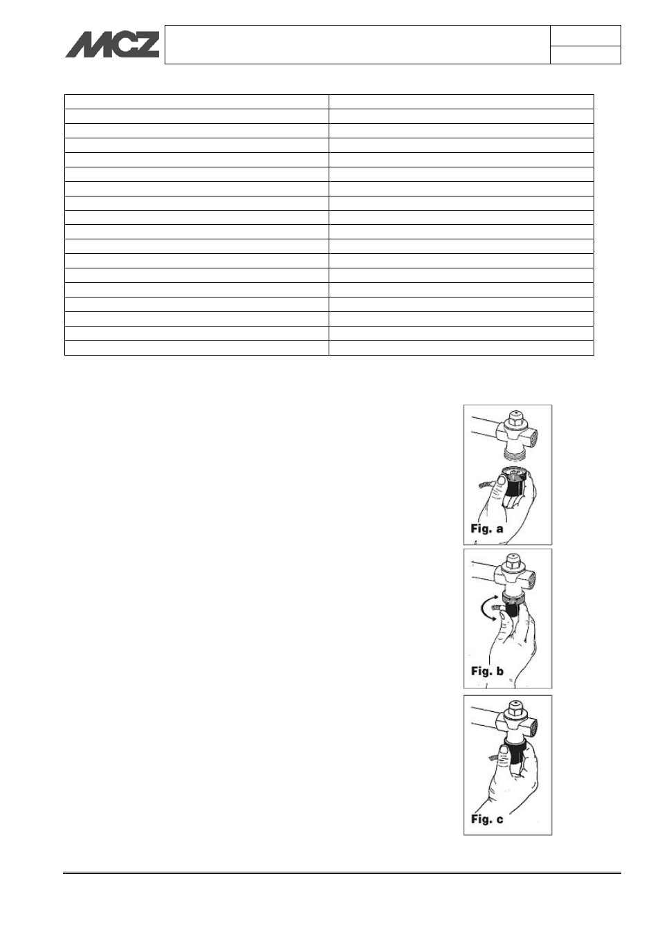
distance not exceeding 0.5 m. After having assembled the valve on the
pipe, respecting the flow sense indicated on the valve body (fig.e),
house the part connected to the sensor in its housing (see position 8 of
fig. d). Therefore screw the knurled ring avoiding to tighten it (Fig. a).
Direct the output of the sheath that connects the probe by making the
black cap rotate (Fig. b). Completely tighten the knurled ring (Fig. c).
The diameter of the discharge pipe must correspond to the diameter of
the valve outlet; the maximum length must not exceed 2 m, no more
than two curves are acceptable. If these maximum values are exceeded
(2 curves, 2 m of piping) the diameter immediately superior must be
chosen for the discharge pipe. However, consider that more than three
curves and 4 m of piping are not acceptable. The discharge pipe must
not have upward sections. The discharge pipe of the safety valve must
be created in a way not to stop the regular function of the valves and
not to cause damage to people or objects. In compliance with the
current standards, the discharge of the safety valve must be visible and
channelled into suitable collection pipes.