Electrical connection of the control unit mcz, Line, Inputs (i) – MCZ Hydrotherm 70 User Manual
Page 20: Outputs (u)
INSTALLATION AND USE MANUAL
Chapter 4
page
20
Installation and assembly
Technical service – MCZ GROUP S.p.A. all rights reserved - Reproduction prohibited
4.5.2. Electrical connection of the control unit MCZ
The thermal adjuster is made up of:
Recessed control unit.
Fruit box.
Thermal probe and well (included in the supply)
For correct operation and to avoid any damage to electrical/electronic
parts:
Place the device in a dry place far from direct heat sources.
Place the PROBE by using the specific manifold (optional) in a
way to read the correct temperature of the boiler, avoiding
direct or indirect contact with the flame.
Place the container-box without the control unit body.
The installation and the electrical connections must
be made by a qualified electrician using adequate
equipment.
Connection to the power supply network must be
made only after connecting the wires in the terminal
board.
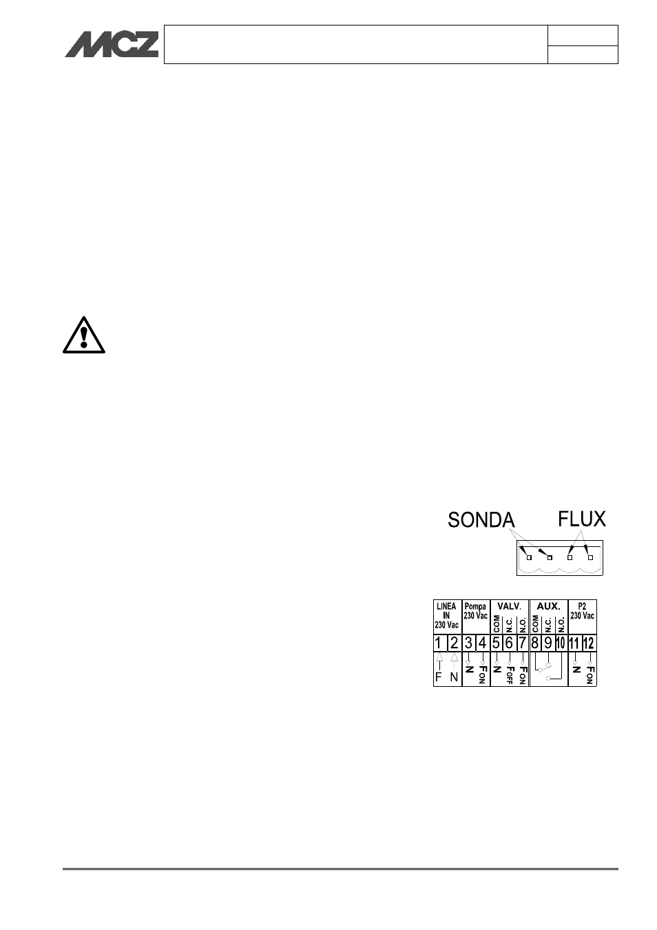
LINE
Connect the 230 Vac
10% -~50 Hz electric line to the terminal boards
[1] and [2] to power the control unit. Protection fuse T3.15 A
INPUTS (I)
Probe: Connection to the probe of the fireplace stove that detects the
system temperature.
Temperature range 0 – 100 °C
Flux: ON/OFF permission for the connection of a flow switch or
thermostat of a boiler for domestic hot water
OUTPUTS (U)
Pump: Connection of the water circulation pump in the heating
system. Terminals [3] and [4]
Valv:
Connection of a possible 2/3 wire solenoid valve serving as
domestic valve. Terminals [5] [6] and [7]
Aux:
Auxiliary connection to connect a gas boiler to control the
shutdown. Terminals [8] [9] and [10]
P2:
Connection to the domestic hot water circulation pump.
Terminals [11] and [12]