Wiring diagram, Wiring color cord – Subaru Robin RGV12100 User Manual
Page 49
5
3
2
4
(AC output)
(AVR)
1
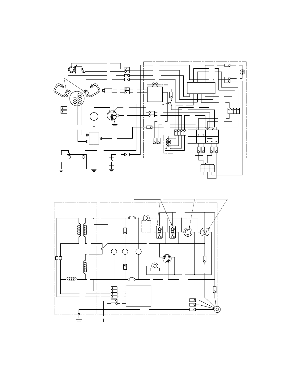
CONTROL BOX
Fuel cut
Ignition coil
Auto choke
(Bimetal)
Electric
starter
Oil pressure
switch
Regulator
Magnetic
switch
Charge
coil
Exciting
coil
-
+
Battery 12V
Grn/Y
Grn
LBlu
Gry
W
Key
switch
to earth
terminal
ST Relay
Connector
(Remote control)
Gry
R15
Blk15
Grn
W
W
W
Blk/W
Gry
Gry
Blk
R
Blk/W
Blk
R
Grn/Y
Grn/Y
Grn
Grn
Org
R
Org
Org
LBlu
LBlu
LBlu
Brn
Y
Org
R
W
W
W
W
W
W
W
OFF
-M +M B L.IG ST
ON
START
R/W
Idle
solenoid
1
Electronic control unit
2
13
3
12
4
11
5
10
6
9 8 7
Blk
Y
Y
Blk
Grn/Y
Grn/Y
Idle control
switch
Idle
control
unit
Oil pressure
warning lamp
(Red)
LGrn
Org
Blk
Blu
Blk
R
R
Blk
W
W
W
LGrn
Grn/Y
Grn/Y
Grn/Y
Grn/Y
Brm
CONTROL BOX
GENERATOR
No-fuse breaker
Voltmeter
Hour meter
Pilot lamp
V
Hr
PL
Earth(Ground)
terminal
Brush
Auxiliary
Winding
Field
Winding
AC Winding
AC Winding
AVR
Exciting coil
(Engine)
Idle
control
unit
AC otuput
receptacle(120V)
AC output
receptacle(120V)
AC output
receptacle(120/240V)
AC output
receptacle(120/240V)
Y
Y
REC1
REC2
REC3
REC4
REC5
W
W
W
W
X
X
Y
Y
H
H
G
G
G
G
G
Key switch -M
Idle control unit 3
Blk
Y
Y
W
W
LGrn
Brm
46
Wiring color cord
LGrn
R/W
Blk/R
Blk
Black
Brn/W
Brown/White
R
Red
Blk/W
Black/White
Grn
Green
W
White
Blu
Blue
Grn/W
Green/White
Y
Yellow
LBlu
Light blue
Org
Orange
Pik
Pink
Brn
Brown
Gry
Gray
Grn/Y
Green/Yellow
Light green
Red/White
Black/Red
11. WIRING DIAGRAM
(
RGV12100
)