Nexen TC920V 964356 User Manual
Page 17
14
FORM NO. L21268-C-1013
4. USER INTERFACE (continued...)
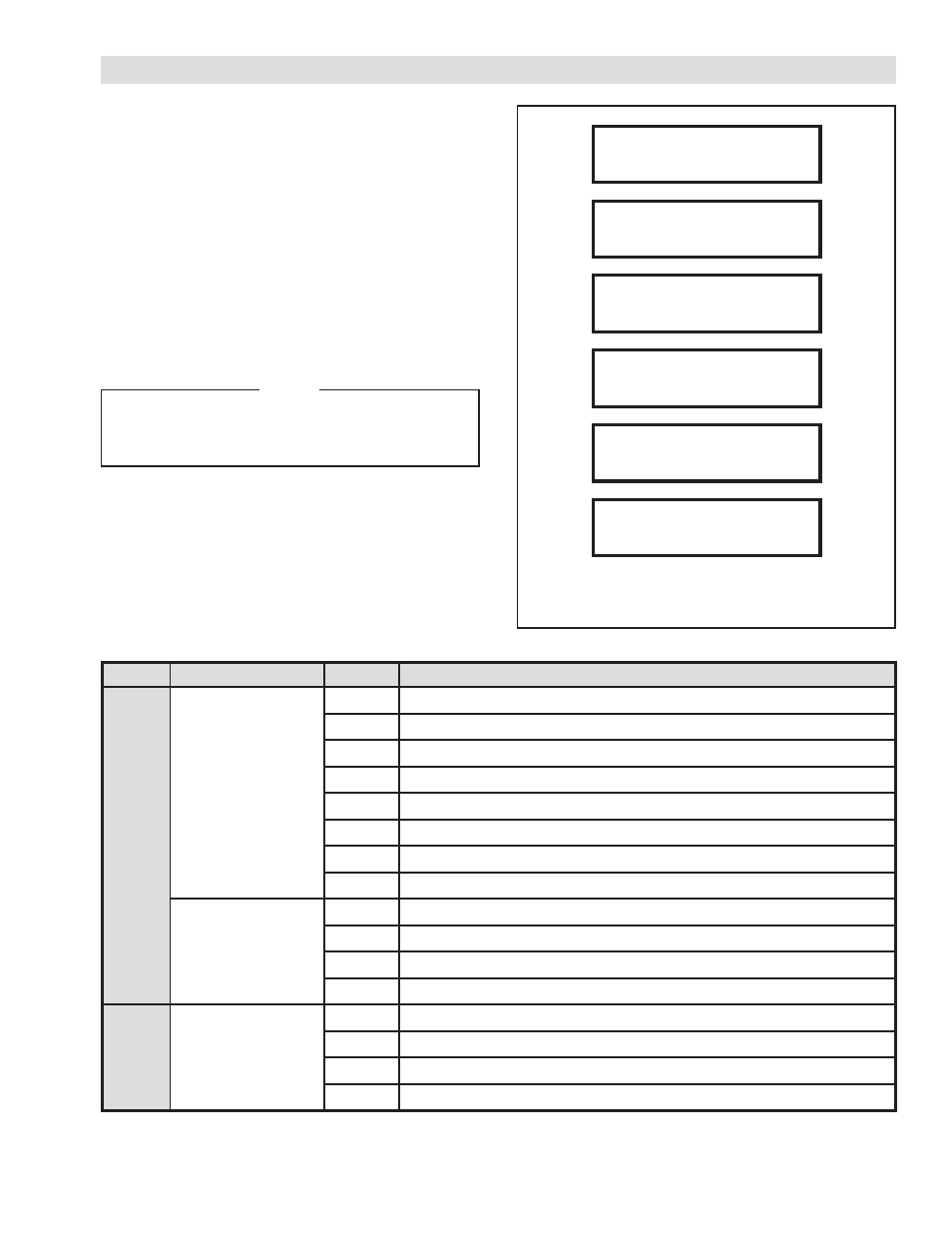
4.3 RUN TIME STATUS
When not in programming mode, the front panel display
shows current operating conditions of the TC920V. The fol-
lowing items can be displayed by pressing the r or s key.
1. Tension Set point & Control Output
2. Individual Sensor Tension Output
3. Relay input 1 status
4. Relay input 2 status
5. Relay output status
6. Diameter and Velocity (Only available when Digital
Diameter measurement is enabled)
NOTE
In Relay input/output status display mode,
the status of the relay is displayed as:
* = ON, - = OFF
FIGURE 4.15
DISPLAY INDICATION PAGES
TABLE 1 RELAY STATUS INDICATORS
TEN. SET
OUTPUT
NO1-TEN
NO2-TEN
RELAY1
RELAY OUT
RELAY2
DIAM.
VEL.
40lbF
20%
20lbF
20lbF
76543210
---*--*-
3210
--*-
3210
--*-
100mm
100m/min
Relay Set
Number Relay Function
Input
RELAY 1
0
Automatic contact
1
Memory reset
2
Acceleration/Deceleration correction
3
Splice
4
Emergency Stop
1
5
Control Output On
6
(not used)
7
(not used)
RELAY 2
0
(not used)
1
(not used)
2
Diameter Reset
3
Diameter Hold
Output
RELAY OUT
0
(For Internal Use)
1
Zero tension contact
2
Over-tension contact
2
3
Auto Mode
1
May also be used for external auto/manual switch or contact for acceleration correction
2
Can be used for minimum diameter (Memory DIP switch MSW2–1)