Tc920v unit descriptions – Nexen TC920V 964356 User Manual
Page 5
2
FORM NO. L21268-C-1013
2. TC920V UNIT DESCRIPTIONS
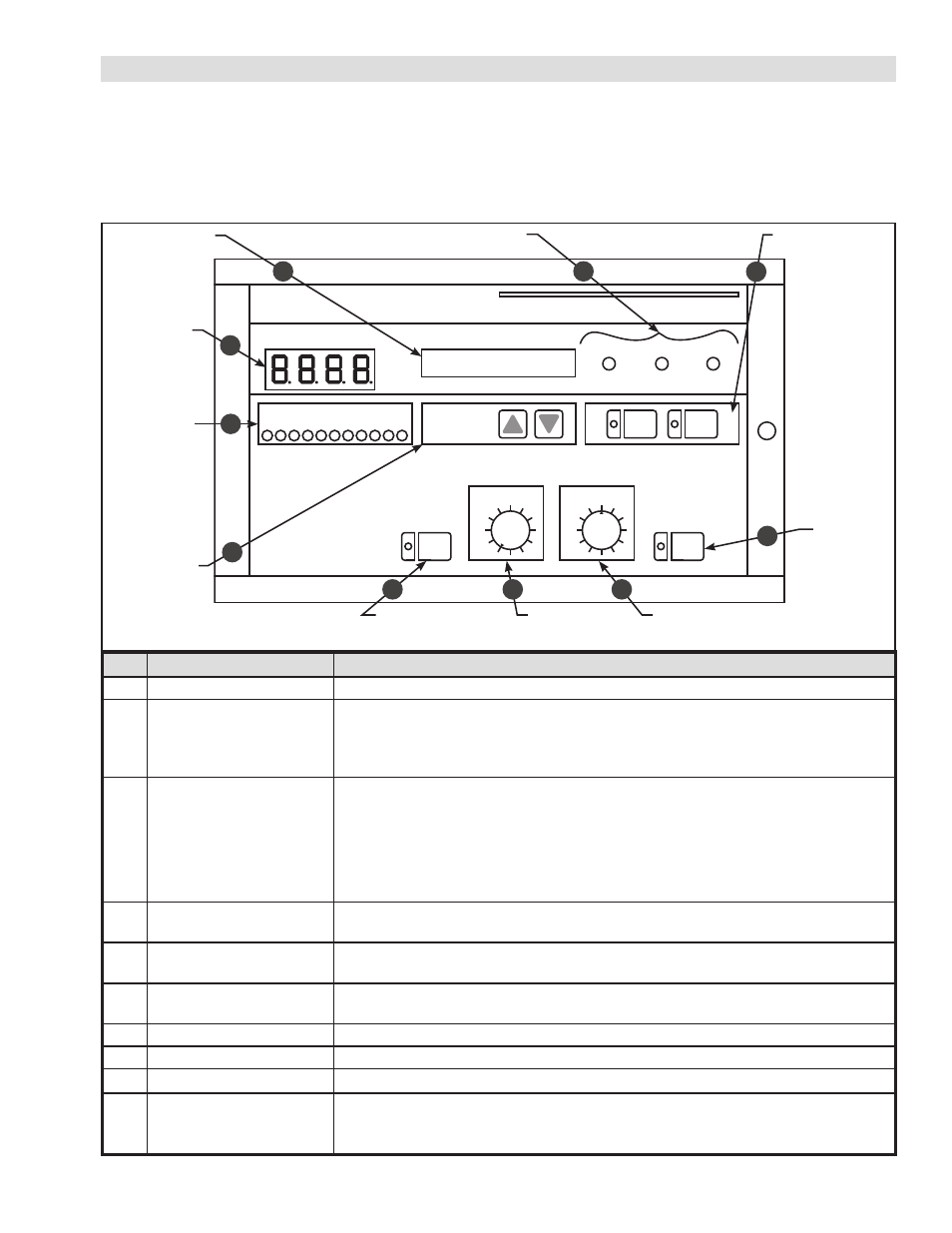
2.1 FRONT PANEL
The front panel is the primary means of controlling and monitoring the TC920V by the machine operator. From the front
panel, the machine operator can monitor the output level, tension measurement, and machine state. The operator can set
the tension set point or run the TC920V in manual mode. Setup and calibration of the TC920V is not directly accessible
from the front panel, limiting the operator’s control of the unit during operation of the machine.
CONTROLLER TC920V
TENSION
START AUTO STOP
OUTPUT
DISP/SEL
AUTO
0
50
100%
OUTPUT
ON
MAN
AUTO
MAN
DIA
METER
FIGURE 2.1 Front Panel
Total Tension
Display
Output Level
Indicator LED
LCD Display
Selection Keys
New Shaft Diameter
Setting Keys
Tension Setting
AUTO
Manual (output)
Setting MAN
Output
ON/OFF
Key
LCD Display Unit
Settings, Output,
Parameters
Operation Status
Indicator Lamps
Auto/Manual Mode
Selection Keys
1
5
10
9
8
7
4
6
3
2
Item
Function
Description
1
Total Tension Display
Indicates the measured total tension.
2
LCD Display Unit
Displays the set tension value and control output during normal operation. In run
mode, the r and s keys are used to cycle between pages of display information
showing individual sensor tension readings, and input and output relay status.
Refer to section 4.3 for details.
3
Operation Status
Indicator Lamps
When the unit is in automatic mode, the indicator lamps show the run state of the
unit. One of the following lamps will be lit in Automatic mode:
START: Controller is in standby or in Start Mode and has not entered automatic
tension control status. Control output is at start level.
AUTO: Control output is in automatic tension control mode.
STOP: Control output is under control of Stop Mode level.
4
Auto/Manual Mode Keys
Selects between Manual control and Automatic control mode. Indicator lamp on
respective keys indicates current mode.
5
Output Level
Indicator Graph
Eleven LEDs indicate 0 to 100% output. The LEDs indicate increments of 10%.
The value is rounded to the nearest 10% increment.
6
Display/Select Keys
Under normal operation, keys select the contents of LCD Display. In setup modes,
the keys are also used to adjust parameter values.
7
Output ON/OFF Key
Toggles the control output ON and OFF. When lit, the control output is ON.
8
Manual Setting
(MAN)
This dial is used to adjust the output when in Manual mode.
9
Tension Setting
(AUTO)
This dial is used to set the tension set point.
10
New Shaft Diameter
For paper splicing control, this key is used to change the paste level. When the key
is pressed, the paste level is set. Use the r and s keys to enter value, and press
key again to save the change.