Nexen TC920V 964356 User Manual
Page 19
16
FORM NO. L21268-C-1013
4. USER INTERFACE (continued...)
4.5 MEMORY SWITCH SETTINGS
The TC920V has a special set of software memory switches (MSW) that operate as virtual DIP switches which must be
set depending on certain operating conditions. The memory switches (MSW) are selected and modified similar to the
standard parameters as detailed in Section 4.4. When setting a memory switch, a “*” represent a switch parameter in the
ON position, while a "–" represent a switch in the OFF position.
MSW0–0
Enables the use of the Control Output input contact. If enabled, the input contact overrides the
OUTPUT ON key on the front panel. When the setting is Enabled and the Control Output input
contact is ON, the Control Output is enabled.
MSW0–1, 2
Selects the function of the Terminal 8 input contact. Operation setting:
E M S : Contact enables the Emergency Stop Mode. Refer to Section 7.4.3
A / M : Contact controls selection of Automatic and Manual operation mode. When the contact
is ON, Automatic mode will be selected.
ACEL: Contact is ON during machine acceleration and operates the Acceleration Gain Correction
Mode as detailed in Section 7.2.
MSW0-3
Sets whether to use the digital diameter measuring function with an encoder.
MSW0-4
Always set to OFF.
MSW0-5
Always set to OFF.
MSW0-6
Sets whether the buzzer sounds when a key on the front panel is pressed.
MSW0-7
Always set to OFF.
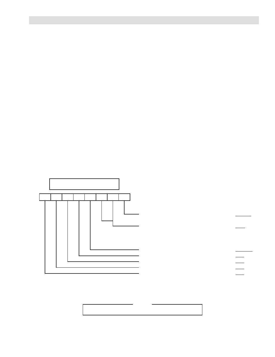
MEMORY DIP SWITCH 0 (MSW0)
7
6
5
4
3
2
1
0
0: Control Output ON Contact
1-2: Terminal 8 Contact Function
3: Diameter Measuring function
4: Not Used
5: Not Used
6: Key Operation Buzzer Sound
7: Not Used
: Disabled
: –
–
: –
*
:
*
–
:
* *
: Enabled
:
:
: ON
:
Enabled
EMS
A/M
ACEL
Reserved
Disabled
OFF
OFF
OFF
OFF
7 6 5 4 3 2 1 0
– – – – – – – –
MSW0
ON (*) OFF (–)
NOTE
The underline indicates a position set at the factory.
2 1