Nexen TC920V 964356 User Manual
Page 22
19
FORM NO. L21268-C-1013
5. CALIBRATION
1. To begin the calibration procedure, the unit must be
in standby with the START indicator lit.
If the unit is in Manual mode, press the AUTO button.
Remove the web and make sure no other objects are
resting on the sensor roll.
2. Open the front panel and set the DIP switch SW1
position 8 to the ON position.
The display will change to the step selection screen
to indicate the system is in calibration mode (Refer to
Figure 5.1). The underlined selection shows the step
in the calibration procedure. Use the r and s keys on
the front panel to scroll through the step numbers
and press SET to select the step. The unit will return
to this screen after each step of the calibration
procedure and advance to the next step when
successful. Press SET, to start the next step in the
procedure. At any point, if the DATA key is pressed,
the step selection screen will reapear without any
changes being made. (Refer to the Troubleshooting
section for help with any error messages.)
3. Step 0: Decimal Point Selection: The first step is to
select the decimal point precision.
0: None 10 to 1000 lbF
1: First 10.0 to 1000.0 lbF
2: Second 1.0 to 100.0 lbF
Select a number using the r and s keys and press
SET to set the selection. (Refer to Figure 5.2)
FIGURE 5.1
FIGURE 5.2
FIGURE 5.3
FIGURE 5.4
FIGURE 5.5
FIGURE 5.6
ZEROSPAN–ADJ.
0: 1: 2: 3: 4:
DOT POSITION
0: 1: 2:
TENSION FS
100 100lbF
TENSION SPAN
100 100lbF
ZERO ADJ.
SET:GO DATA:RET
SPAN ADJ.
SET:GO DATA:RET
Stretch a rope on the center of the
roll following the path of the web.
Sensor
Roll
Hang a
known
weight.
Change Value
Change Value
Current Value
Current Value
4. Step 1: Full Scale Setting: Set the numeric value for
the maximum tension set point. (Refer to Figure 5.3)
5. Step 2: Tension Value Setting for Calibration: Set
the tension value the system will be calibrated with.
The calibration span weight must be equivalent to
50% or more of the Full Scale set in step 4. (Refer to
Figure 5.4)
NOTE
If the Full Scale Setting is changed, zero and
span much be readjusted.
6. Step 3: Zero Adjustment: Ensure web is removed
from sensor roll before proceeding. Press SET to
start the Zero Adjustment phase of the calibration.
The display will read "ZERO ADJUSTING" while
calibrating, and will read "END ZERO ADJ." when
completed. After completion of adjustment, press
DATA to return to the calibration menu. (Refer to
Figure 5.5)
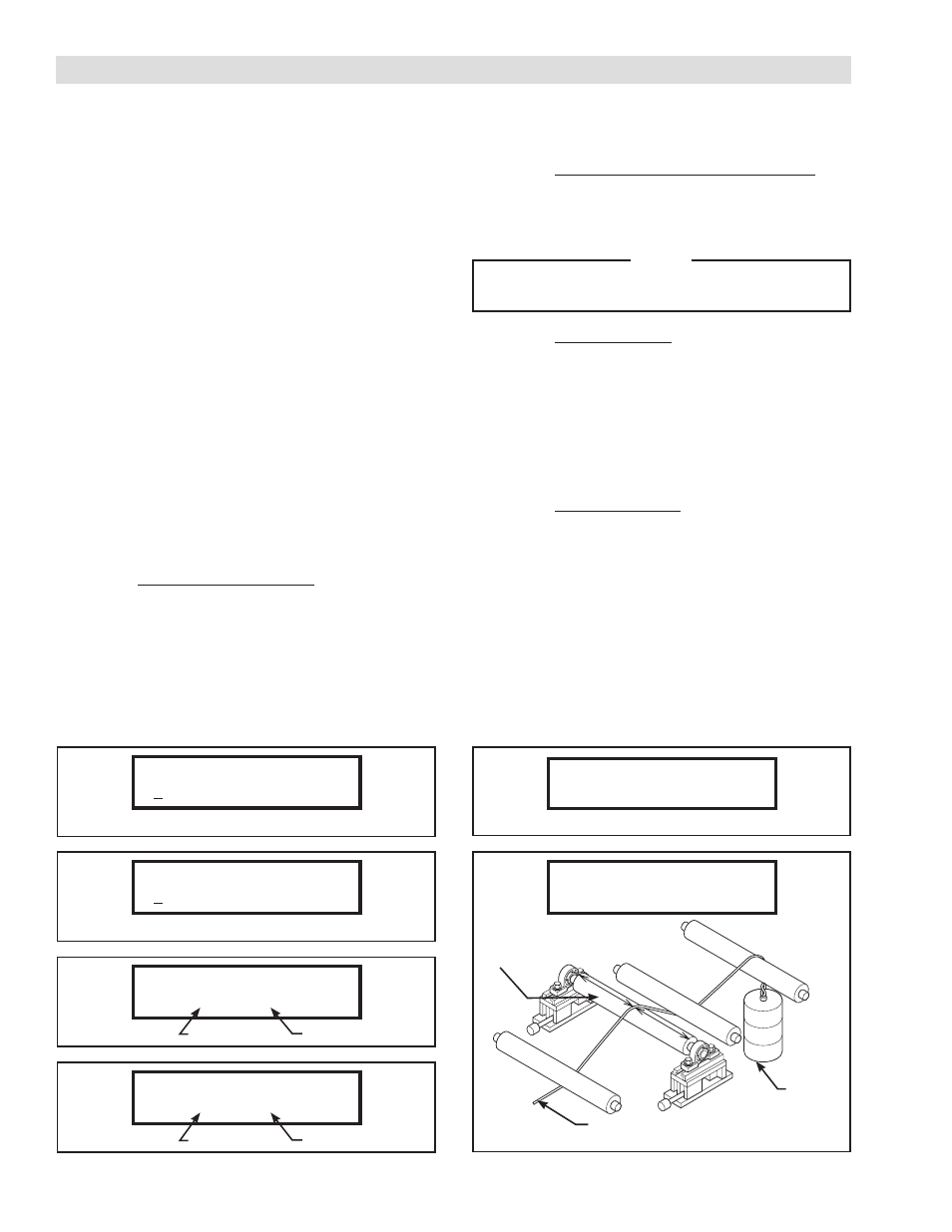
7. Step 4: Span Adjustment: Hang the weight that
was specified in Step 5 (Refer to Figure 5.6). Press
SET to start the Span Adjustment phase of the
calibration.
Display will read "SP. ADJUSTING" during the span
adjustment, and will read “END SPAN ADJ.” when
completed. After completion of the adjustment,
press DATA to return to the calibration menu.
8. Open the front panel and return DIP Switch SW1
position 8 to the OFF position.