Wiring a mechanical limit switch, Wiring a limit sensor, 33 sv7 hardware manual – Applied Motion SV7-C-CE User Manual
Page 33
33
SV7 Hardware Manual
920-0012F
12/18/2014
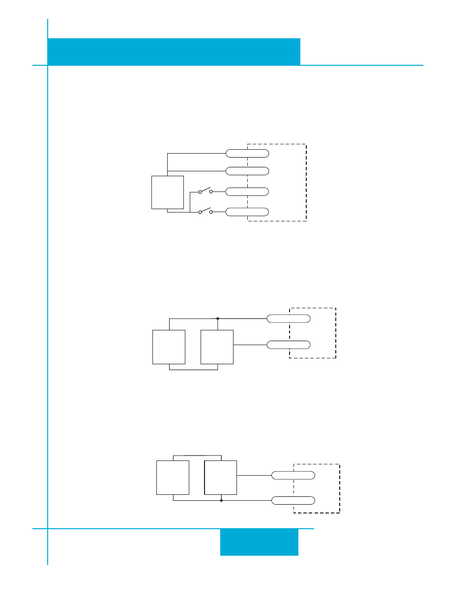
Wiring a Mechanical Limit Switch
You can use normally open or normally closed limit switches. Either way, wire them as shown here.
Be sure to set the polarity using the Si Programmer™ for Si™ drives or
QuickTuner™ software for the
SV7-S and SV7-Q.
Wiring a Limit Sensor
Some systems use active limit sensors that produce a voltage output rather than a switch or relay
closure. These devices must be wired differently than switches.
If your sensor has an open collector output or a sinking output, wire it like this:
If the sensor output goes low at the limit, select the option “closed” (in the software). If the output is
open, or high voltage, choose “open”.
Other sensors have sourcing outputs. That means that current can flow out of the sensor output,
but not into it. In that case, wire the sensor this way:
IN/OUT1
+
DC
Power
Supply
–
Limit
Sensor
output
+
–
CW LIMIT+
CW LIMIT-
IN/OUT1
+
DC
Power
Supply
–
Proximity
Sensor
output
+
–
CW LIMIT+
CW LIMIT-
IN/OUT1
+
12-24
VDC
SUPPLY
-
CW LIMIT+
CW LIMIT-
CCW LIMIT+
CCW LIMIT-