Interfacing to a motion controller, Encoder outputs, 39 sv7 hardware manual – Applied Motion SV7-C-CE User Manual
Page 39
39
SV7 Hardware Manual
920-0012F
12/18/2014
Connecting a Motion Controller with Analog (±10V) Output
Interfacing to a Motion Controller
In some applications, servo control is provided by a motion controller and the drive simply obeys a
velocity or torque command. The industry standard for this command signal is ±10V. In most cases,
the encoder signals from the motor must feed back to the controller. The SV7-S-AF servo drive
includes a special Motion Controller Feedback board to accomodate such applications.
To connect an SV7-S-AF to a motion controller, you must make a cable to connect the motion con-
troller to the DB9 connector on the motion controller feedback board. Diagrams are shown below.
Providing the motion controller with access to the analog command, servo enable, alarm reset, and
fault output signals requires an additional cable to the SV7’s DB25 connector. See the diagram
below for pin numbers. Note: this diagram assumes that FAULT IN of the motion controller
can accept a sinking signal.
You’ll also need to use our
QuickTuner™ software to set the drive for torque or velocity mode, to
set the scaling and offset of the analog input, and to configure the motor.
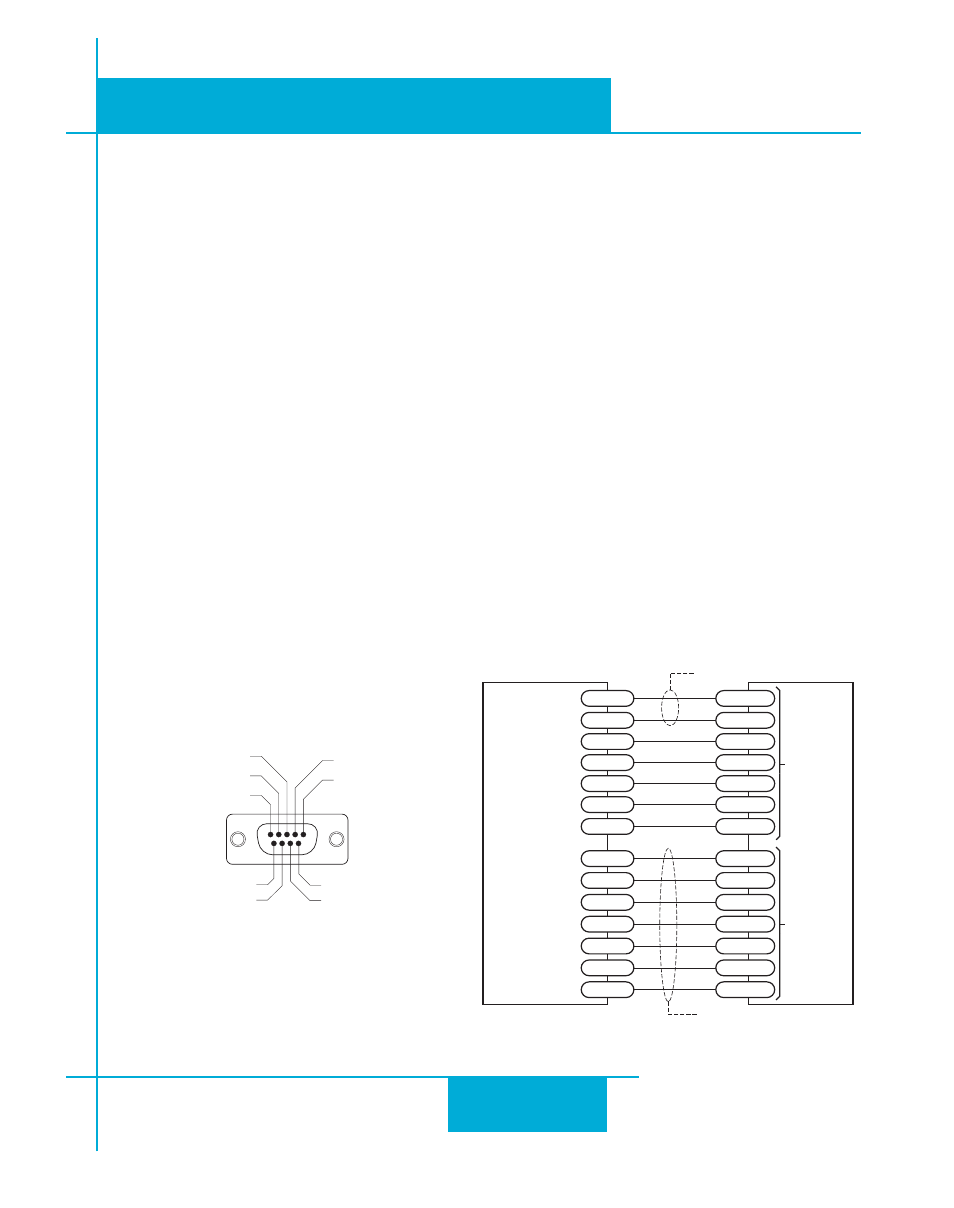
Encoder Outputs
If you are using the SV servo in torque or velocity mode with a servo controller, you may need
to feed the encoder signals back to the controller. The DB-9 connector on the motion controller
feedback option board includes encoder output signals for this purpose.
Front View of Motion Controller Feedback
(MCF) connector
encoder A+ OUT (1)
encoder A- OUT (2)
encoder B+ OUT (3)
(5) encoder Z+ OUT
(4) encoder B- OUT
GND (7)
encoder Z- OUT (6)
(8) Not Connected
(9) Not Connected
SV Servo Drive
Signal+
ANALOG+
DB-25 CONNECTOR
DB-9 CONNECTOR
Connect cable shield to connector shell
Connect cable shield to connector shell
Signal-
GND
A+
A+ OUT
A-
A- OUT
B+
B+ OUT
B-
B- OUT
Z+
Z+ OUT
Z-
Z- OUT
GND
GND
Motion
Controller
1
1
2
3
4
5
6
7
13
RST OUT
X4/RESET
EN OUT
X3/ENABLE
6
12-24VDC
XCOM
8
COM
YCOM
17
FAULT IN
Y3/FAULT
16
7