Splay link position at the z5300 j flying frame – d&b J-Series User Manual
Page 12
Within the J-Series Rigging system the following types of Locking pins
are used:
J-Series Loudspeaker (J8/12 and J-SUB)
•
Locking pins 10 mm for the cabinet Front links. Linked in pairs with a
steel wire and undetachably fixed to the cabinet.
•
Locking pins 11 mm for the Splay (Rear) link at the central rear
rigging strand. Linked in pairs with a steel wire and undetachably
fixed to the cabinet.
•
Locking pin 8 mm at the wheel board undetachably fixed to the
wheel board with a steel wire.
J Load adapter/J Flying frame
•
Locking pins 12 mm to attach the J Load adapter to the Flying
frame. Linked in pairs with a steel wire and undetachably fixed to
the Load adapter.
•
Locking pin 11 mm for the Splay link and the cable pick of the frame
to fix the respective component in its park position. Connected to the
fixing bolt of the respective component with a rue ring cotter and a
steel wire.
•
Locking pins 10 mm for the two additional Front links at the Flying
frame. Linked together in pairs with a steel wire.
3.4.
Splay link position at the Z5300 J Flying frame
WARNING!
The fixing bolt of the frames Splay link is stressed by the
full load of the array.
It is essential the bolt is fitted correctly and secured by
the ring cotter when altering the position of the Splay
link.
Ensure the ring cotter is properly locked.
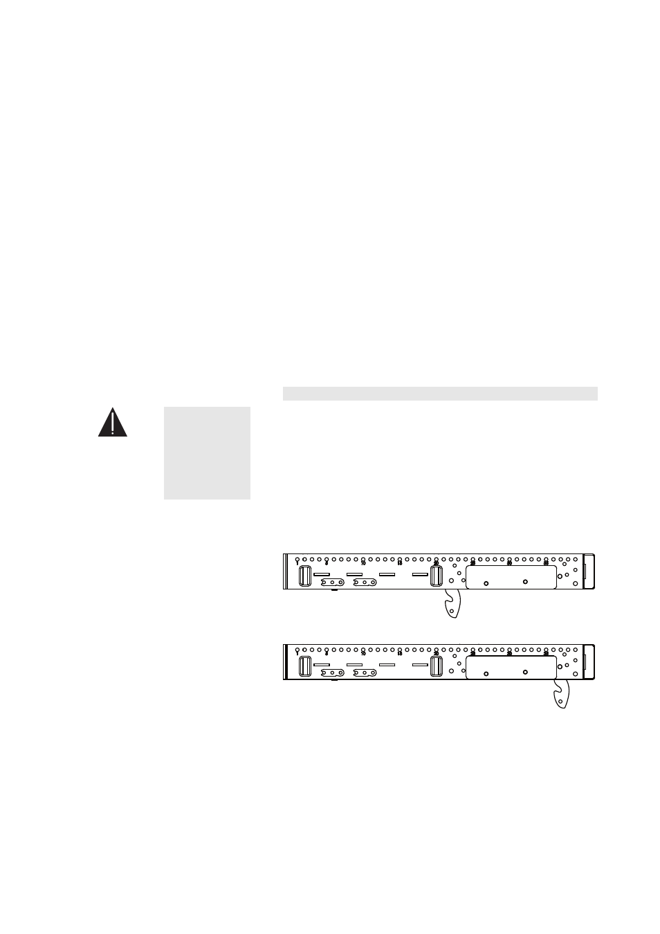
Depending on the type of cabinet (J8/J12 or J-SUB) to be attached to
the J Flying frame the position of the frames Splay link needs to be
altered.
Fig. 11: Splay link frame – J8/J12 position
Fig. 12: Splay link frame – J-SUB position
To change the Splay link position proceed as follows:
J-Series Rigging manual
(1.3 EN)
Page 12 of 34