Derigging, Variant 3: j-sub array, Variant 4: j-series ground stacks – d&b J-Series User Manual
Page 26: Limitations for j-series ground stacks, Preparations, 4 variant 4: j-series ground stacks
Hoisting and securing of the array
When all the mechanical adjustments, system checks and safety checks
have been made the array can be hoisted up to its operating position.
When hoisting the array, ensure that the loudspeaker cables do not get
caught anywhere. The cables can be strapped together with the motor
cable to form a loom while the system is hoisted.
The chain hoist motors must raise the system slowly and evenly so that it
does not swing or move from side to side during hoisting.
When the array is in its final operating position the secondary safety
must be applied. A detailed description is given in 3.6 Secondary safety
on page 15.
4.2.2. Derigging
To lower the array and dismantle it, follow the assembly instructions in
reverse order. The same safety instructions apply.
4.3.
Variant 3: J-SUB Array
The set up of SUB arrays is carried out in the same manner as
described in section 4.2 Variant 2: J-SUB and J8/J12 Arrays from page
22 (Steps 1 – 21 - Fig. 33a-k.
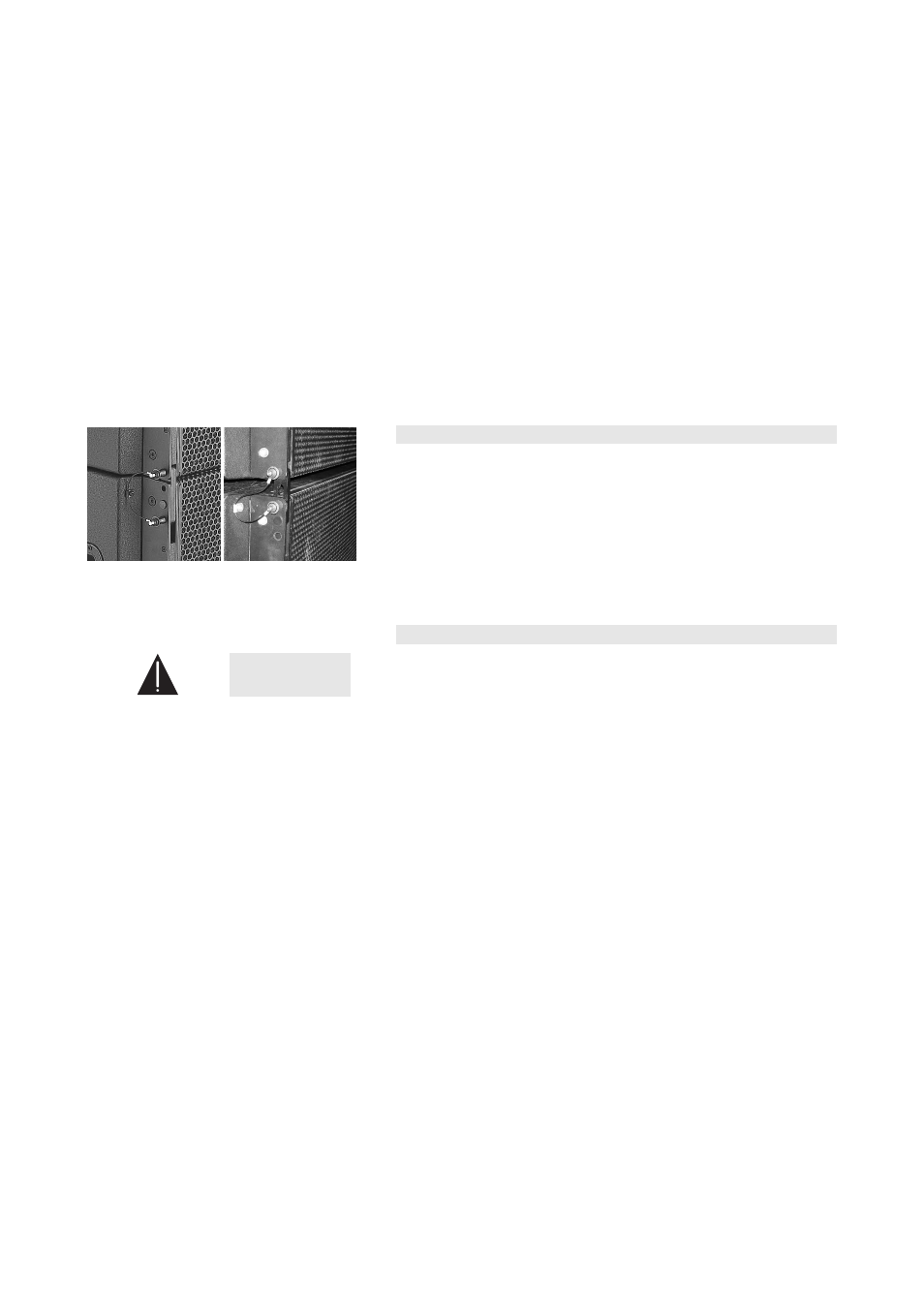
If desired J-SUB arrays can also be curved. Depending on the chosen
socket for the Locking pins of the J-SUB Front links a splay angle of 0°
(Fig. 36a) or 2° (Fig. 36b) can be applied to the front of the cabinet. The
splay angle of 2° is achieved by the slot in the J-SUB Front links and will
only be effective when the array gets lifted.
4.4.
Variant 4: J-Series ground stacks
WARNING!
Ground stacked set ups must always be secured against
movement and possible tipping over.
4.4.1. Limitations for J-Series Ground stacks
The following limitations apply:
•
A maximum of six J-TOP (J8/J12) cabinets mounted on the J Flying
frame.
•
A maximum of four J-SUB cabinets and six J-TOP (J8/J12) cabinets
mounted on the J Flying frame on top of the J-SUB cabinets.
4.4.2. Preparations
For both applications the Splay link of the frame must be fitted in J-SUB
position. Check the position of the Splay link and alter the position if
necessary as described in section 3.4 Splay link position at the Z5300 J
Flying frame on page 12.
J-Series Rigging manual
(1.3 EN)
Page 26 of 34
a)
b)
Fig. 36: J-SUB Front Link
Setting of the Locking pins for 0° or 2°