d&b J-Series User Manual
Page 25
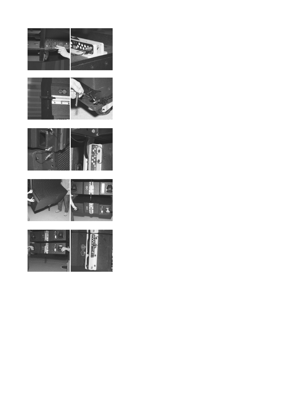
Attach the J8/J12 cabinets (Fig. 35a-j)
31. Lift the array to a suitable height using the hoists.
32. Fold out the Splay link of the frame (J8/J12 position) - Fig. 35a.
33. Preset the Locking pin at the central rigging strand at the rear of the
first cabinet to the 0° position - Fig. 35b.
34. Fold out the Splay link of the first cabinet - Fig. 35c.
35. Prepare the Front links of the cabinet - Fig. 35d.
36. With one person at each side of the cabinet remove the wheel
board and lift the cabinet with the front grill facing towards the
front. Insert the Front links into the rigging tracks at the front of the
frame.
37. Fix the cabinets Front links at the frame with the Locking pins - Fig.
35e.
38. Lift the back of the cabinet until the Splay link of the frame has
hooked over the Locking pin at the rear rigging strand of the
cabinet.
39. Secure the Splay link with the second Locking pin using the 4°
position. - Fig. 35f.
40. Attach all further cabinets in the same manner. Proceed as follows:
•
Preset the desired Splay angle at the respective cabinet (0°
... 6°) at the central rigging strand at the rear of the cabinet
by inserting the respective Locking pin. 7° degrees settings
are done when the cabinet is being attached to the array –
see Fig. 35g – cabinet can swing out to the front.
•
Prepare the Front links as shown in Fig. 35d.
•
Fold out the Splay link. (not necessary for lowest cabinet of
the array)
•
Lift the cabinet and insert the Front links into the cabinet
above and fix the Locking pins.
•
Lift the back of the cabinet until the its Splay has hooked
over the Locking pin of the cabinet above.
•
Secure the Splay link with the second Locking pin using the
hole below the preset pin.
Rig the cabling
41. Connect the flying cables and link cables according to the number of
amplifier channels and cabinets used. If the amplifiers are already
wired and powered on, using their System check function or channel
mute switches and a test signal the correct function and routing of all
channels and cabinets can be verified.
J-Series Rigging manual
(1.3 EN)
Page 25 of 34
a)
b)
c)
d)
e)
f)
g)
h)
i)
j)
Fig. 35: Preparation and attachment of the J8/
J12 cabinets