Variant 1: j8/j12 array, Preparations and order of assembly, Variant 1: j8/j12 array fitting the j flying frame – d&b J-Series User Manual
Page 18
4.1.
Variant 1: J8/J12 Array
4.1.1. Preparations and order of assembly
The array can be assembled on the ground completely without the need
of lifting the cabinets by hand. On their wheel boards the cabinets can
be easily moved into position and joined together.
1. Prepare the flying cables and link cables according to the number of
amplifier channels and cabinets used.
2. Arrange the cabinets in the right order and direction to be joined
together as follows:
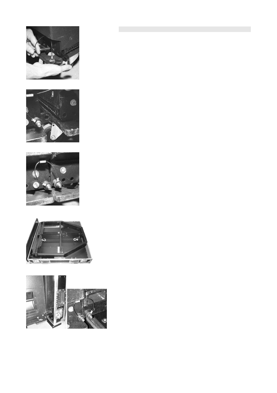
Joining the cabinets together (Fig. 25a – c)
3. With one person on each side of the cabinets first release and
remove both Locking pins of the cabinet's Front links. The links can
be accessed through the holes in the wheel boards and slid out to
their stop position. (Fig. 25a)
4. Insert one pin to the respective socket to fix the Front links in place.
(Fig. 25b)
5. Insert the Front links into the front rigging strands of the next cabinet
and lock them with the second pin (Fig. 25b).
Repeat steps 3 to 5 in the same manner until all cabinets are joined
together.
Note: For an easy attachment of the Flying frame it is advisable to
connect at least two cabinets before fitting the Flying frame to the top
cabinet as described below.
Fitting the J Flying frame (Fig. 26, Fig. 27a/b; Fig. 28)
The J Flying frame can be fitted to the top cabinets Front links using the
E7441 Touring case. The Touring case enables the J Flying frame to be
positioned in the exact vertical level of the cabinet Front links. To do so
the Flying frame must be positioned with the hole grid of the center bar
facing down and the front of the frame facing towards the wooden
baseboard of the Touring case.
6. Prepare the Front links of the top cabinet in the same manner as
done in step 3 and 4.
7. With one person on each side open the case and tilt the J Flying
frame upright using the wooden baseboard of the Touring case and
position it towards the top cabinet of the column.
8. Release the velcro strips of the Touring case which hold the Flying
frame in place.
9. Move the cabinets towards the frame until the Front links of the first
cabinet are completely inserted into the front tracks of the Flying
frame. (Fig. 27a)
10. Insert and lock the Locking pins of the cabinet to the respective holes
of the Flying frame. (Fig. 27b)
J-Series Rigging manual
(1.3 EN)
Page 18 of 34
Fig. 26: J Flying frame within the E7441
Touring case
a)
b)
Fig. 27: J Flying frame assembly
a)
b)
c)
Fig. 25: Front links assembly