d&b J-Series User Manual
Page 19
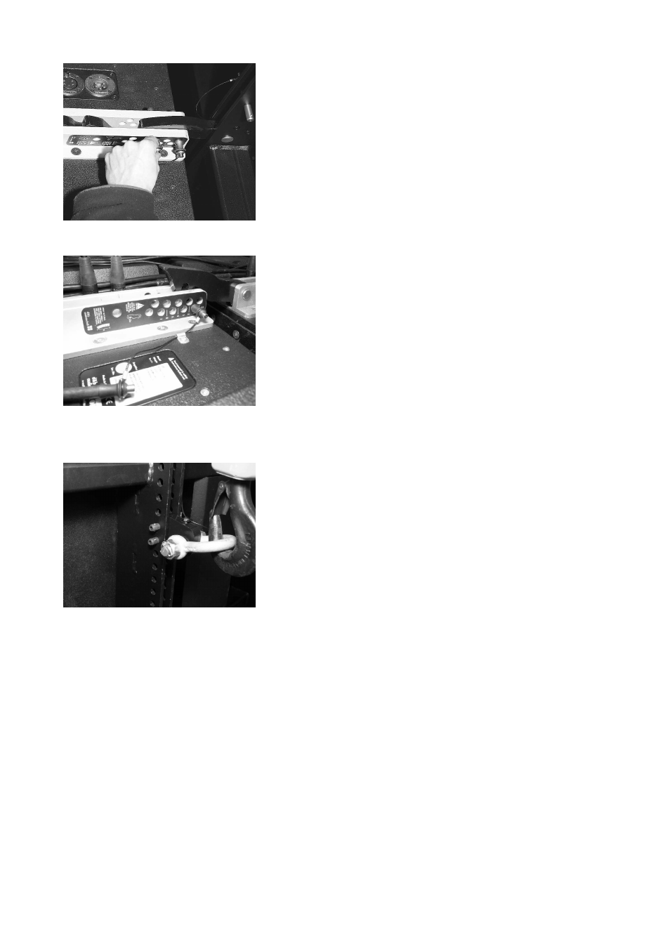
11. Release and remove both Locking pins of the central rigging strand
at the rear of the top cabinet.
12. Release and remove the Locking pin of the frame's Splay link and
fold it out.
13. Attach the Splay link to the central rigging strand at the rear of the
top cabinet and lock it with the two pins of the cabinet (0° and 4°
hole - Fig. 28) and remove the Touring case.
Rig the cabling
14. Connect the flying cables and link cables according to the number of
amplifier channels and cabinets used.
Preset the splay angles (0° ... 6° settings; Fig. 29)
Note: The maximum splay angle of 7° is not being preset. For the 7°
position both Locking pins will be fixed later during the lifting procedure
described from step 21 when the full splay is reached.
15. Preset the splay angle of each cabinet according to your ArrayCalc
simulation by inserting one pin to the respective hole of the central
rigging strand.
16. Release the other pin which is holding the Splay link in place and put
it aside. This pin is used to secure the Splay link when fixing the splay
angles in a later step.
17. Swing off the Splay link of the cabinet to the central rigging strand
of the next cabinet.
Attach the pick point
18. Depending on the type of suspension (single or dual hoist set up as
described in section 3.5 on page 13) attach the J Load adapter to
the center bar of the J Flying frame and connect the hoist. (Fig. 30)
Attach the secondary safety device
19. At this point of the set up we recommend to attach the secondary
safety device using the Z5303 J Safety chain set as described in
section 3.6 Secondary safety on page 15.
Checking the actual set up
20. Before continuing with the set up it is recommended to check the
actual status of the assembly as follows:
•
Check the assembly of the Flying frame to the first cabinet
(Front and Splay links) and ensure all Locking pins are
properly locked.
•
Check the attachment of the Load adapter(s) to the Flying
frame and ensure all Locking pins are properly locked.
•
Check the assembly of the secondary safety device at the
Flying frame. (refer to section 3.6 on page 15)
•
Check the assembly of all Front links to both sides of the
cabinets and ensure all Locking pins are properly locked.
•
Check the preset splay angles.
J-Series Rigging manual
(1.3 EN)
Page 19 of 34
Fig. 28: Splay link of the frame connected
to the first cabinet
Fig. 30: J Load adapter fitted and hoist
connected
Fig. 29: Preset the splay angles