Suspension of the z5300 j flying frame, J load adapter – d&b J-Series User Manual
Page 13
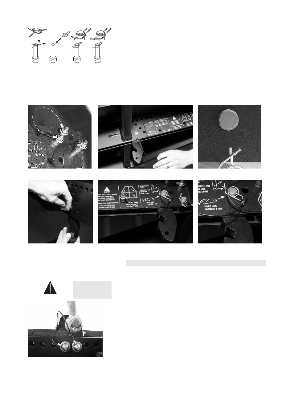
Release
Remove/
Fit
Snap in
Lock
Fig. 13: Function of the ring cotter of the
fixing bolt (schematic diagram)
Assembly
1. First alter the position of the additional Locking pins [1.5] as shown
in Fig. 14 - Step 1.
2. Release and remove the Locking pin of the Splay link and fold out
the Splay link.
3. Unlock and remove the ring cotter of the fixing bolt.
4. Remove the fixing bolt while holding the Splay link.
5. Move the Splay link to its new position and insert the fixing bolt.
6. Secure the fixing bolt with the ring cotter and ensure the ring cotter
is properly locked.
Step 1
Step 2
Step 3
Step 4/5
Step 6
Fig. 14: Altering the Splay link position of the frame
3.5.
Suspension of the Z5300 J Flying frame
3.5.1. J Load adapter
WARNING!
Before attaching the Load adapter check the 3.25 t.
shackle is properly fitted to the Load adapter and
secured against loosening.
Fig. 15: J Load adapter
The suspension of the J Flying frame is carried out using one or two J
Load adapter fitted with a 3.25 t shackle, depending on the chosen type
of suspension (Single or Dual hoist set up).
The Load adapter(s) are attached to the center bar of the Flying frame
and fixed with the two Locking pins 12 mm of the Load adapter.
Ensure the Load adapter is properly attached to the
center bar of the frame and both Locking pins are
inserted and locked securely before lifting the array.
J-Series Rigging manual
(1.3 EN)
Page 13 of 34