d&b J-Series User Manual
Page 24
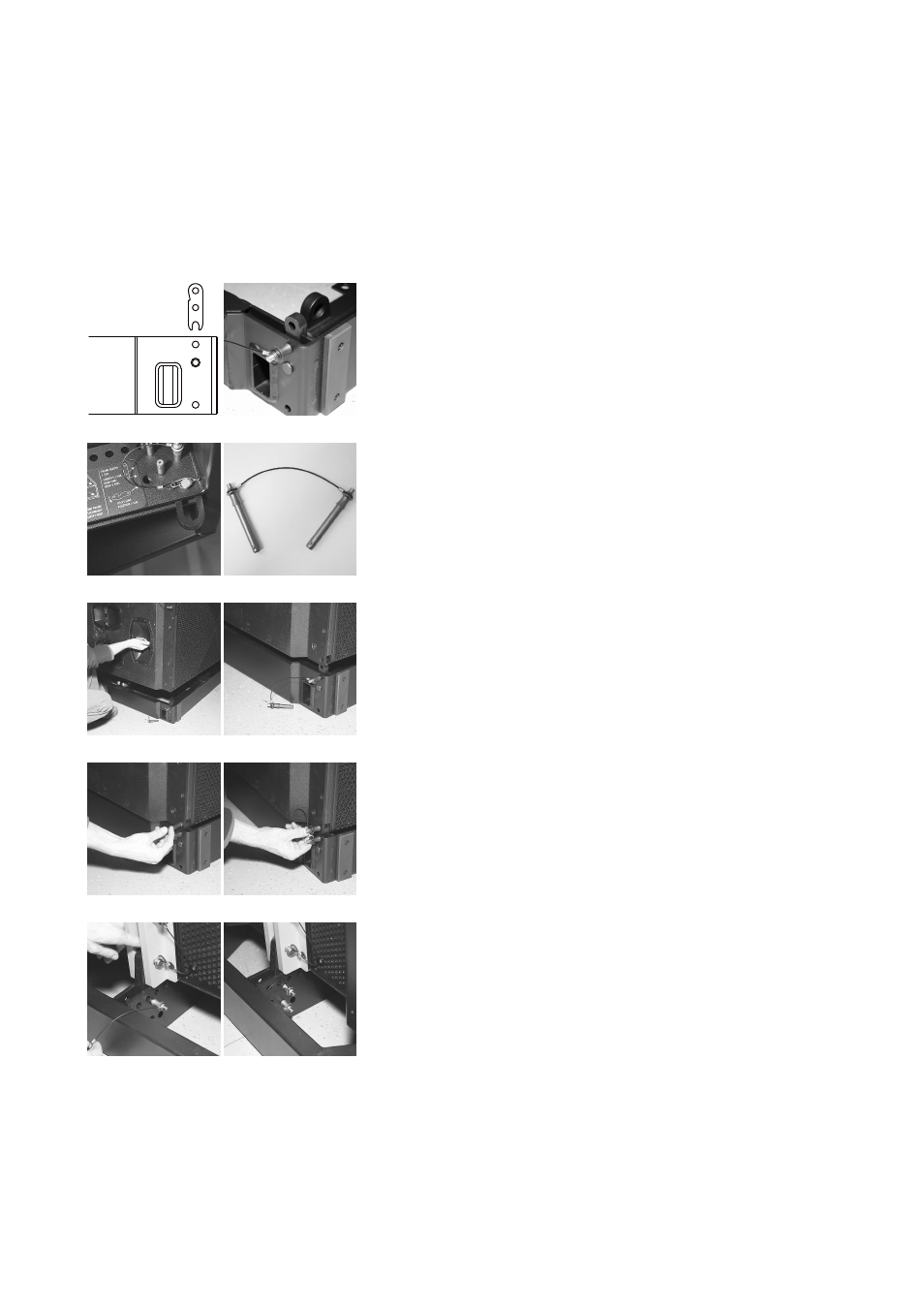
Preparation and assembly of the second Flying frame
(Fig. 34a – j)
To allow J8/J12 cabinets to be attached below J-SUB cabinets a second
J Flying frame must be used as an adapter.
The J Flying Frame can be picked up by the flown J-SUB column directly
from the E7441 Touring case. For this purpose the Flying frame needs
to be positioned in the case with the hole grid of the center bar facing
upwards and the front of the frame facing towards the wooden
baseboard of the case.
Note: The graphics opposite are without the Touring case.
Prepare the second Flying frame as follows:
23. The Splay link of the frame must be fitted in J8/J12 position. Alter
the position if necessary as described in section 3.4 Splay link
position at the Z5300 J Flying frame on page 12.
24. Remove the additional Front links [1.7] together with the Locking pins
from the park position at the frame.
25. Attach the Front links at the top of the front tracks of the frame and
fix them with the Locking pins. Observe the direction of attachment -
Fig. 34a/b.
26. Release and slide out the cable pick [1.4] by removing the respective
Locking pin and refit the Locking pin back to its socket - Fig. 34c.
27. Remove the additional Locking pins [1.5] from the park position at
the frame - Fig. 34d. These Locking pins are used to fix the Rear link
of the lowest J-SUB cabinet to the frame in a later step.
28. Lower and position the prepared J-SUB assembly on the Flying
frame in the Touring case - Fig. 34e/f.
29. Connect the Front links to the lowest J-SUB cabinets using the
Locking pins - Fig. 34g/h.
30. Fix the Rear link of the respective J-SUB cabinet to the frame using
the additional Locking pins [1.5] - Fig. 34i/j.
J-Series Rigging manual
(1.3 EN)
Page 24 of 34
a)
b)
c)
d)
e)
f)
g)
h)
i)
j)
Fig. 34: Preparation and assembly second
Flying frame