Single hoist set up, Dual hoist set up, 2 single hoist set up – d&b J-Series User Manual
Page 14
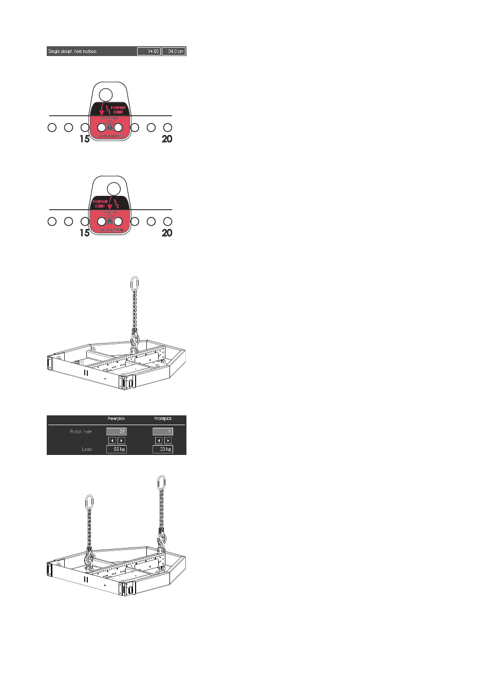
Fig. 16: ArrayCalc
Hole position for Single hoist set up
Fig. 17: Direction of the J Load adapter
for full grid (1/1 Pickpoint Detent)
Shown: Hole 16
Fig. 18: Direction of the J Load adapter
for half grid (1/2 Pickpoint Detent)
Shown: Hole 16,5
Fig. 19: Single hoist set up
Fig. 20: ArrayCalc
Hole positions for Dual hoist set up
Fig. 21: Dual hoist set up
3.5.2. Single hoist set up
When suspending the array from a single pick point (Single Pick point
Operation) the following limits apply:
Maximum system weight of 1025 kg (2260 lb) or
accordingly:
•
Max. 16 x J-TOP cabinets (J8/J12)
•
Max. 8 x J-SUB cabinets
In "Single Pickpoint Operation" the position of the J Load adapter
defines the vertical aiming of the whole array.
The corresponding hole position is calculated using ArrayCalc (Fig. 16)
and can be set in a 1/2-hole resolution at the top of the center bar of
the J Flying frame.
The J Load adapter allows a full grid (1/1 Pickpoint Detent) or a half
grid (1/2 Pickpoint Detent) setting depending on its direction of
attachment (Fig. 17/18).
The frame's hole index marked on one side of the center bar of the
frame is the reference for the direction of the Load adapter.
Attaching the Load adapter
1. Choose the appropriate hole position in the J Flying frame center
bar according to the ArrayCalc simulation and attach the J Load
adapter correspondingly.
If ArrayCalc displays a half numbered hole setting (half grid) turn
the J Load adapter correspondingly (refer to Fig. 18)
2. Connect the Z5305 J Hoist connector chain to the 3.25 t Shackle of
the J Load adapter.
3.5.3. Dual hoist set up
When suspending the array from two pick points the following limits
apply:
Maximum system weight of 1.5 t (3300 lb) or accordingly:
•
Max. 24 x J-TOP cabinets (J8/J12)
•
Max. 14 x J-SUB cabinets
With Dual hoist setup the vertical aiming of the array will be set by
trimming the hoist motors after the array is fully assembled and lifted to
its operating position. The corresponding hole positions of the Load
adapters is calculated using ArrayCalc - Fig. 20.
Attaching the Load adapter
1. Choose the appropriate hole positions for the Front and Rearpick in
the J Flying frame center bar according to the ArrayCalc simulation
and attach the J Load adapters correspondingly (Direction: Full grid
1/1 Pickpoint Detent).
2. Connect one Z5305 J Hoist connector chain each to the 3.25 t
shackle of the respective J Load adapter.
J-Series Rigging manual
(1.3 EN)
Page 14 of 34