Z5300 j flying frame center bar – d&b J-Series User Manual
Page 8
2.1.2. Z5300 J Flying frame center bar
[2.1]
[2.2]
[2.3a] [2.3b]
[2.4b] [2.4a]
[2.5b]
[2.5a]
[2.6]
[2]
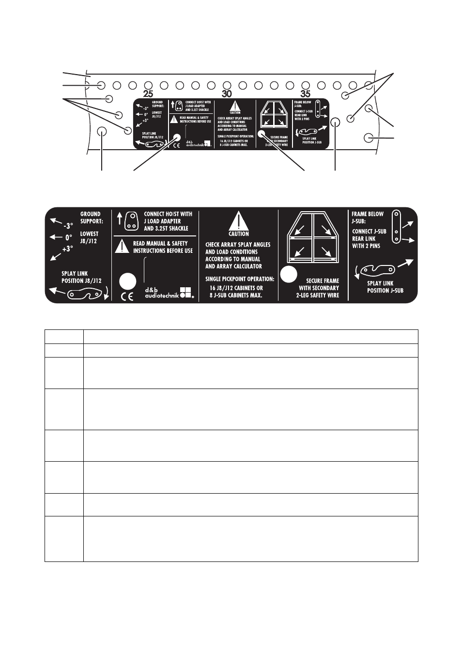
Fig. 2: Z5300 J Flying frame center bar with user instructions
Fig. 3: Z5300 J Flying frame user instructions
Position Description
[2]
Center bar of the Flying frame with user instructions.
[2.1]
Main hole grid at the top of the center bar with a total of 39 holes numbered with an increment of five.
Using the J Load adapters the Flying frame can be suspended from one or two pick points. (please refer to
the sections 3.5.2 Single hoist set up on page 14 and 3.5.3 Dual hoist set up on page 14)
[2.2]
Hole grid ground stack: when J8/J12 cabinets are attached to the top of the frame this hole grid indicates
the possible settings of –3°, 0° or +3° for the Splay link of the lowest cabinet. The Splay link is to be
connected to the frame using the additional Locking pins [1.5]. (refer to section 4.4 Variant 4: J-Series
ground stacks from page 26)
[2.3a]
[2.3b]
Fixing point for the frame's Splay link in J8/J12 position. (refer to section 3.4 Splay link position at the
Z5300 J Flying frame on page 12). The additional hole [2.3b] is used to fix the Splay link in its park position
using the respective Locking pin.
[2.4a]
[2.4b]
Fixing point for the frame's Splay link in J-SUB position. (refer to section 3.4 Splay link position at the Z5300
J Flying frameon page 12). The additional hole [2.4b] is used to fix the Splay link in its park position using the
respective Locking pin.
[2.5a]
[2.5b]
Fixing point for the Cable pick (O-Ring). The additional hole [2.5b] is used to fix the O-Ring in its park
position using the respective Locking pin.
[2.6]
Fitting the Flying frame below a J-SUB cabinet (Mixed J-Series array with J-SUB cabinets at the top of the
column) these two holes are used to fix the Rear link of the respective J-SUB cabinet to the frame using the
two additional Locking pins [1.5]. (refer to section 4.2 Variant 2: J-SUB and J8/J12 Arrays from page 22)
These holes can also be used to park the two additional Locking pins [1.5] during transport.
J-Series Rigging manual
(1.3 EN)
Page 8 of 34