d&b J-Series User Manual
Page 20
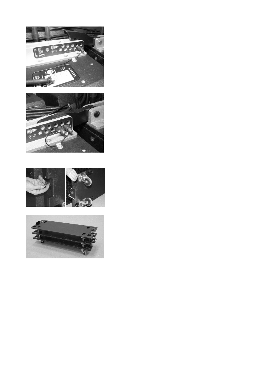
Fix the splay angles
21. Lift the Flying frame using the hoist until the first Splay link has
hooked over the preset Locking pin. (Fig. 31a/b)
22. Lower the Flying frame until the second securing Locking pin can be
inserted into the hole below the preset pin. (Fig. 31b)
23. Repeat this procedure of lifting and lowering cabinet by cabinet until
all splay angles are fixed and the Splay links are secured with the
Locking pins.
Alternatively this procedure can be applied to a group of cabinets in
one step. In this case lift the Flying frame using the hoist until all Splay
links of the group have hooked over their preset Locking pins (0° ... 6°).
Lower the Flying frame and insert the remaining securing Locking pins
until all splay angles are fixed and all Splay links are secured.
Remove the wheel boards (Fig. 32a-c)
The wheel boards have a fixed pin at one side and a removable pin to
the other side and they can be fitted to the cabinet either way around.
Using the recessed holes on top the wheel boards can easily be stacked
and stored aside.
24. Rise the array until the wheel board of the top cabinet is in an
accessible height.
25. With one person on each side of the cabinets first release the pin
while holding the wheel board.
26. Slightly fold off the board and move it towards the other side to
release the fixed pin.
27. Take off the wheel board.
28. Remove all accessible boards in the same manner.
29. Lift the array to get access to the remaining wheel boards and
remove them in the same manner.
Check the whole set up
30. Check the assembly of the Splay/Rear links at the rear of the
cabinets and ensure all Splay links are secured with two pins..
31. Check the wiring.
If the amplifiers are already wired and powered on, using their
System check function or channel mute switches and a test signal the
correct function and routing of all channels and cabinets can be
verified.
Hoisting and securing the array
When all the mechanical adjustments, system checks and safety checks
have been made the array can be hoisted up to its operating position.
When hoisting the array, ensure that the loudspeaker cables do not get
caught anywhere. The cables can be strapped together with the motor
cable to form a loom while the system is hoisted.
The chain hoist motors must raise the system slowly and evenly so that it
does not swing or move from side to side during hoisting.
When the array is in its final operating position the secondary safety
must be applied. A detailed description is given in 3.6 Secondary safety
on page 15.
J-Series Rigging manual
(1.3 EN)
Page 20 of 34
a)
b)
Fig. 31: Fixing the splay angles
a)
b)
c)
Fig. 32: Removing the wheel boards