Paxton Superchargers Dodge Viper RT/10 User Manual
Page 27
9-3
P/N: 4809646
©2006 Paxton Automotive
All Rights Reserved, Intl. Copr. Secured
17FEB06 v2.0 92-96Viper(4809646v2.0)
5.
The supplied yellow wire will be used
as the “trigger” wire and should be con-
nected to terminal #85 using a slide
connector. The other end of the wire
will be connected in section 11.
6.
Run the black wire from terminal #86
on the water pump relay to the
“ground” located beneath it on the
vehicle’s frame.
7.
Connect the fuse holder using a yellow
slide connector to terminal #30 on the
aftercooler pump relay and to the fuse
box power terminal on the front of the
fuse box using the supplied wire and
yellow ring terminal connector.
8.
Use the supplied black wire, ring termi-
nal and butt connector to extend the
water pump ground wire (brown wire
on pump) to the same grounding loca-
tion used for the water pump relay
ground.
9.
Route the red wire from the water
pump to relay terminal #87. Using the
supplied butt connector, attach the red
wire to the positive wire on the water
pump (green wire on the pump).
10. Install the supplied plastic wire loom
around the water pump power wires
and secure.
***NOTE***
Double check that all wires are connected to the proper
relay lugs.
D.
Water Cooler Installation
1.
Remove the two screws securing the
hood release handle to the bumper.
2.
Using sealant, insert the 90° fittings in
the inlet and outlet of the water cooler
and point them towards each other.
4.
Attach the water cooler to the installed
bracket and tighten so that the water
cooler is as far to the passenger’s side
as possible.
***CAUTION***
In the following step, use extreme care when drilling
through the oil cooler flange. If the drill bit slips or
goes through the hole too far, it will damage the radia-
tor, oil cooler or the AC condenser.
5.
Use the unfastened bracket to serve as a
template to drill a 5/16" hole in the top
flange of the oil cooler. Install the sup-
plied 5/16" hardware and tighten.
6.
Connect the outlet of the water pump to
the far side of the water cooler with the
installed 3/4" hose trimmed to fit by
routing a section of hose through the
bumper. Clamp each end.
7.
Route a 3/4" hose from the remaining
fitting on the water cooler between the
radiator and the passenger’s side frame
rail, connect to the 90° fitting installed
on the CAC.
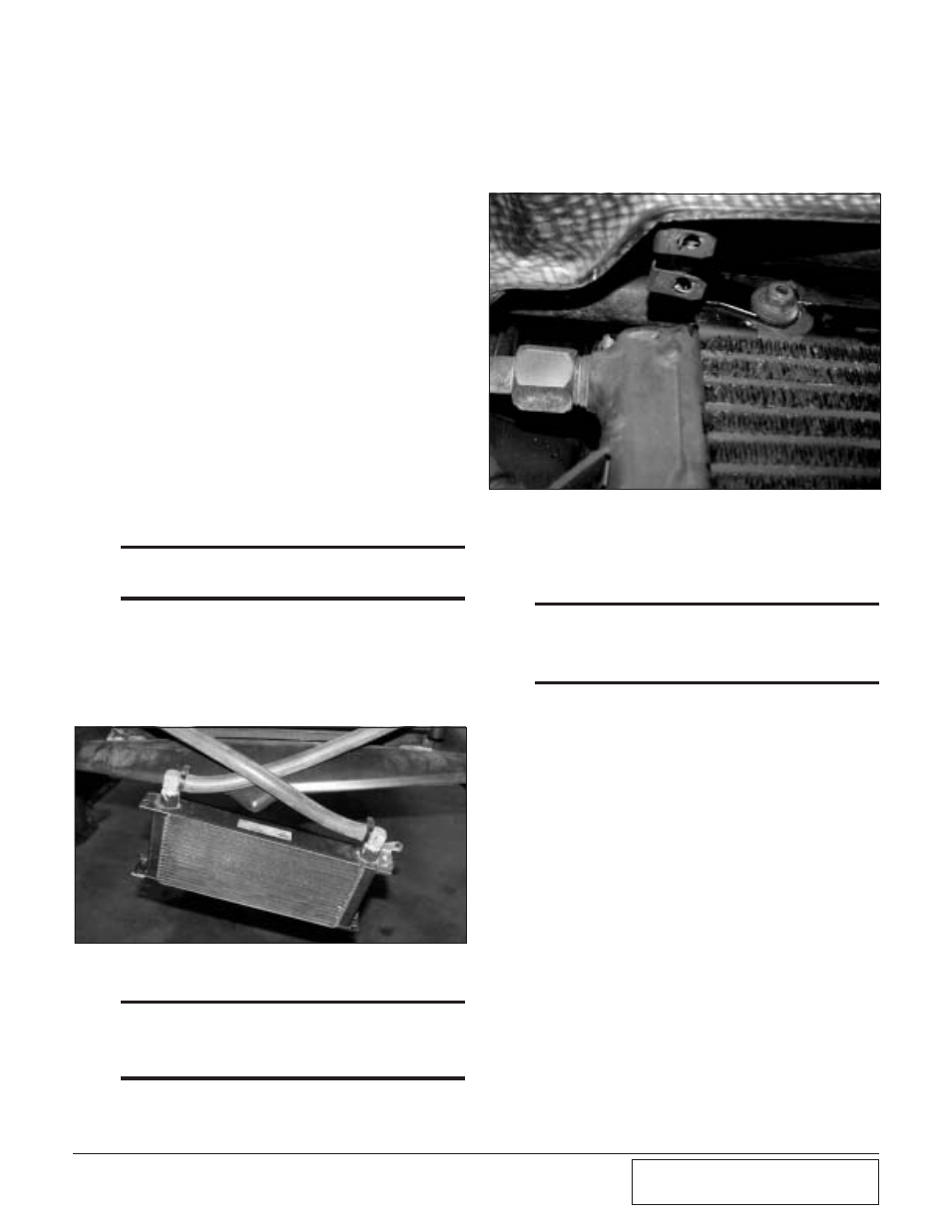
3.
Using supplied hardware, loosely attach
one of the supplied brackets to the pas-
senger’s side oil cooler mounting bolt.
(See Fig. 9-g.) Attach the other bracket
to the water cooler using the supplied
1/4" hardware.
*** NOTE ***
1996 Model Year vehicles use different water cooler
mounting brackets than the earlier cars, make sure to
use the correct pair of brackets as indicated in Figs.
9-f, 9-g.
Fig. 9-f / ('96 Water Cooler Bracket Shown)
Fig. 9-g / ('92-'95 Water Cooler Bracket Shown)