Auxiliary fuel pump assembly installation – Paxton Superchargers Dodge Viper RT/10 User Manual
Page 37
12-1
P/N: 4809646
©2006 Paxton Automotive
All Rights Reserved, Intl. Copr. Secured
17FEB06 v2.0 92-96Viper(4809646v2.0)
Section 12
AUXILIARY FUEL PUMP ASSEMBLY INSTALLATION
12. AUXILIARY FUEL PUMP ASSEMBLY
INSTALLATION
A.
Plumb the supplied fuel pumps in parallel by
connecting the pump inlets to a TEE fitting.
Do the same with the outlets. The pumps are
now configured so that one TEE feeds both
pump inlets and another TEE draws from
both pump outlets.
B.
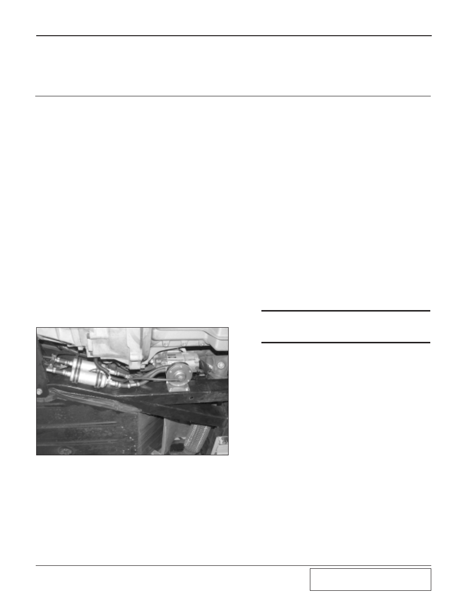
Mount the pumps using the supplied adel
clamps and sheet metal screws on the inside
of the driver’s side frame rail in front of the
large frame plate. Install ring terminal con-
nectors on both ends of the supplied black
wire and fasten underneath one of the sheet
metal screws for later use as fuel pump
ground.
C.
Connect the negative terminals of the fuel
pumps to each other with the supplied wire
and ring terminals.
D.
Connect the previously installed ground
wire to one of the fuel pump ground termi-
nals.
E.
Connect a striped red wire from the ignition
control box to each of the fuel pump posi-
tive terminals using the supplied ring termi-
nal connectors.
Fig. 12-a
F.
Compress the plastic ring (or use a spring
lock disconnect tool) to disconnect the facto-
ry fuel line behind the engine.
G.
Connect the supplied spring lock connector
to the factory fuel line running to the intake
manifold. Attach and route the supplied
5/16" fuel line down to the fuel pump outlet
TEE.
H.
Connect the other supplied spring lock fit-
ting to the factory fuel supply line with the
supplied hose routed down to the fuel pump
inlet TEE.
I.
Install the supplied Fuel Control Unit (FCU)
in the location shown in Fig. 12-b. Route the
fuel lines to the auxiliary fuel pumps.
J.
Cut the auxiliary fuel pump supply (inlet)
line and install a supplied TEE in-line.
Connect the fuel line coming out of the cen-
ter of the FCU to this TEE.
K.
Cut the auxiliary fuel pump discharge (out-
let) line and install a supplied TEE inline.
Connect the fuel line coming out of the side
of the FCU to this TEE.
L.
All of the hose connections should have
clamps installed and tightened using stepless
clamp pliers.
M. Install a 3/16" TEE into the air bypass valve
vacuum line. Attach the supplied 5/32" line
from the FCU cover to the TEE.
N.
Install the supplied plastic wire loom around
the fuel pump power wires and secure.
***WARNING***
Secure fuel lines away from hot or moving objects.
Insulate the fuel line from possible abrasive contact
points.