Timing controller instal, Timing controller installation -1, Timing controller installation – Paxton Superchargers Dodge Viper RT/10 User Manual
Page 35
11-1
P/N: 4809646
©2006 Paxton Automotive
All Rights Reserved, Intl. Copr. Secured
17FEB06 v2.0 92-96Viper(4809646v2.0)
Section 11
TIMING CONTROLLER INSTALLATION
11. TIMING CONTROLLER
INSTALLATION
***NOTE***
The VIOLET wire is not used. Tape up the wire to avoid
confusion.
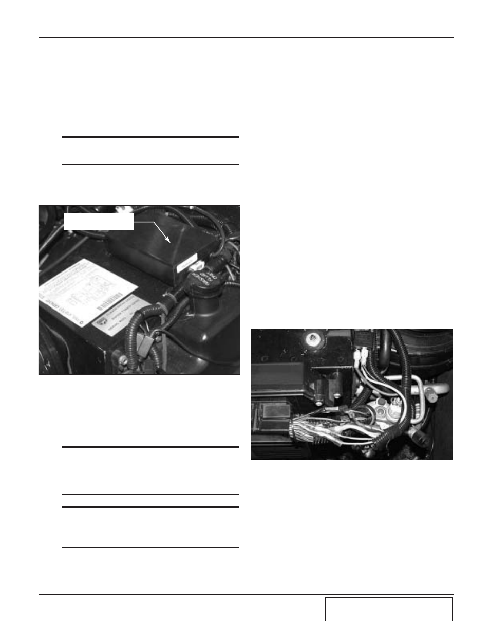
A.
Using the supplied adhesive-backed Velcro,
position the ignition timing control comput-
er as shown in Fig. 11-a.
Fig. 11-a
Fig. 11-b
B.
The vacuum hose on the timing controller
should be connected to the intake manifold
vacuum using the supplied TEE and hose.
C.
Remove the Powertrain Control Module
(PCM) cover. (See Fig. 9-e.)
***
NOTE***
Soldered wire connections are more sound than crimp-
on connectors because they can be inspected. It is up
to the installer to guarantee good connections. If there
is any doubt, or the vehicle performs erratically, solder
and insulate each connection.
***NOTE***
The following steps have some information in paren-
thesis. This information applies to 2000 Vipers only.
Other vehicles are similar, but a factory service manual
should be consulted for verification.
D.
Connect the thin 20GA RED wire to the bat-
tery’s positive switch by the ignition, (Pin
#9, dark blue wire). Use the supplied T-Tap
and spade connector. The yellow water
pump trigger wire (installed in section 9-c)
should also be connected to the same power
source. Use the supplied T-Tap and spade
connector. (See Fig. 11-c.)
E.
Connect the BLACK wire to the signal
ground at the PCM (Pin #4, black with light
blue stripe wire). Use the supplied T-Tap
and spade connector.
F.
Cut the CRANK sensor signal wire (Pin
#24, gray with black stripe wire).
G.
Connect the GRAY wire to the wire leading
to the crank sensor.
H.
Connect the GRAY/BLACK wire to the
wire leading to the PCM crank sensor input.
I.
Cut the CAM sensor signal wire, (Pin #44,
tan with yellow stripe wire).
J.
Connect the TAN wire to the wire leading to
the cam sensor.
K.
Connect the TAN/YELLOW wire to the
wire leading to the PCM cam sensor input.
(See Fig. 11-b.)
IGNITION TIMING
CONTROL COMPUTER
L.
Connect the large 12GA red wire to the bat-
tery (+) positive terminal located at the front
of the fuse box using the 3/8" ring terminal
connector.
M. Reinstall the PCM cover.
N.
The two striped red wires will be used to
power the fuel pumps in the following sec-
tion.