Dut power status measurement, Connecting nudc-4u with pc, Connecting nudc-4u with pcb – Xtramus NuDC-4U V2.1 User Manual
Page 9: Hardware installation
9
2. DUT Power Status Measurement
The following chapter will guide you with wiring/connecting your DUT with NuDC-4U and performing DUT
power status measurement.
Hardware Installation
There are several accessories provided for the connection to most of DC powered device. Please read
the instruction below.
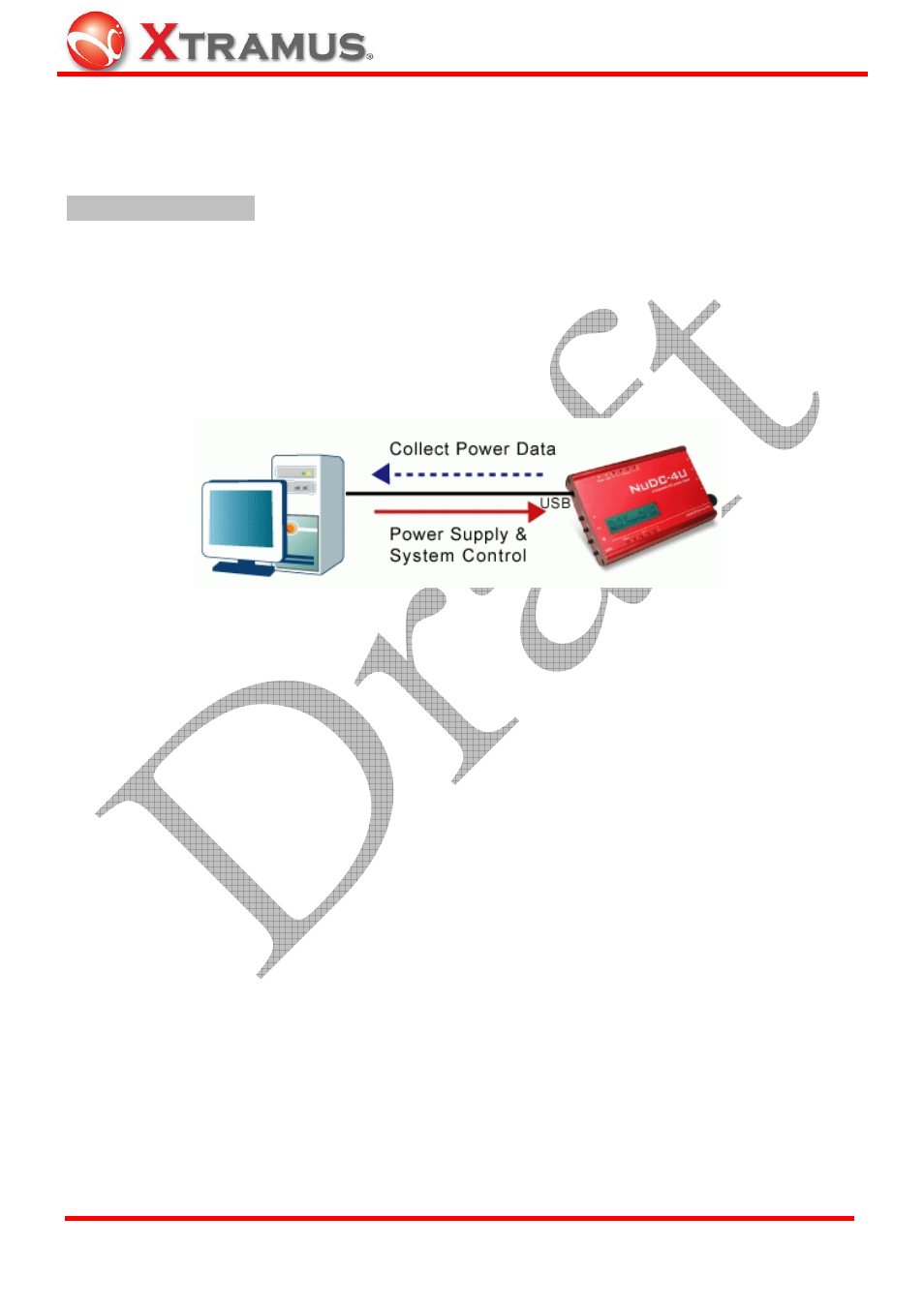
2.1. Connecting NuDC-4U with PC
Connect USB port of NuDC-4U to PC or external power adaptor. If it is connected to PC, PC can control
and also provides power to the NuDC-4U.
2.2. Connecting NuDC-4U with PCB
Connect USB port of NuDC-4U to PC or external power adaptor. If it is connected to PC, PC can control
and also provides power to the NuDC-4U.
¾
Connection of ground pole
In the design of PCB, it should has ground PIN for the test purpose. All components use the same ground
(negative pole) and all ground conductors are linked together electronically. Connect the ground (negative
pole) to the ground connector of NuDC-4U. Several accessory daughter boards can be soldered on the
same PCB and use the same ground PIN.
¾
Connection of diagnostic channel
There are two conductors inside a channel port. Solder the two conductors (C&B) to the both side (Y&Z)
of the component under test by optional accessories. There is no difference if user swaps the sequence of
wire. For example, solder wire C to Y location and solder wire B to Z location.
ASSY-DC L0805, L1206, and L0603 are mini daughter boards with two soldering conductors for soldering
on PCB (printed circuit board). Two conductors of the accessory can be soldered on the surface of PCB.
The three accessories have different conductor width for testing on PCB with different width of soldering
points.
E-mail: [email protected]
Website: www.Xtramus.com
XTRAMUS TECHNOLOGIES
®